121-210-e-ley-en 73 / 104
10秒後にBOOKのページに移動します
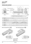
T2 U S1 U S1 T2 Dimensions: Motor Top/Parallel Motor left side parallel type: LEY 2 5 L 32 Motor right side parallel type: LEY R 25 32 Stroke range (mm) 15 to 100 105 to 400 20 to 100 105 to 500 130.5 155.5 148.5 178.5 116 141 130 160 13 13 Size [mm] 25 32 A B C 20 25 D 44 51 EH 45.5 56.5 EV M8 x 1.25 M8 x 1.25 H 24 31 J 17 22 K 14.5 18.5 L 34 40 M O1 8 10 R 46 60 S M5 x 0.8 M6 x 1.0 Size 25 32 92 118 T 1 1 U 40 60 V 26.5 34 Y 47 61 91 117 Size 25 32 S1 T2 1 1 U [mm] Note) When the motor is mounted on the left or right side in parallel, the groove for auto switch on the side to which the motor is mounted is hidden. Note 1) Range within which the rod can move. Make sure a workpiece mounted on the rod does not interfere with the workpieces and facilities around the rod. Note 2) The direction of rod end width across flats (K) differs depending on the products. Rod operating range Note 1) (Stroke + 4 mm) Encoder Z phase detecting position M 2±1 EV V J K Note 2) EH M W Y M U M T Z S X L H thread depth C B + Stroke A + Stroke 4 x O1 thread depth R oD Stroke range (mm) 15 to 100 105 to 400 20 to 100 105 to 500 87 88.2 120 128.2 123.9 116.8 156.9 156.8 82.4 76.6 115.4 116.6 123.5 116.1 156.5 156.1 Without lock With lock Without lock Incremental encoder Absolute encoder With lock W 14.1 17.1 Z 14.1 17.1 Z 15.8 17.1 Z 15.8 17.1 X W X W X W X Z 4 x O1 thread depth R 194 Series LEY Size 25, 32