121-210-e-ley-en 67 / 104
10秒後にBOOKのページに移動します
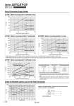
Load: F [N] Stroke [ mm] 100 10 1 Force [N] Torque limit/Command value [%] 500 400 300 200 100 0 10 20 30 40 Force [N] Torque limit/Command value [%] 800 700 600 500 400 300 200 100 0 10 20 30 40 Force [N] Torque limit/Command value [%] 600 500 400 300 200 100 0 10 20 30 40 0 100 200 300 400 500 600 700 800 900 1000 Duty ratio [%] 100 100 (60) 50 (30) 30 (20) Continuous pushing time [minute] . . (1.5) 1.5 (0.5) 0.5 (0.16) Torque limit/Command value [%] 25 or less 30 40 50 .1 The values in ( ) are for a closely-mounted driver. .2 When limiting torque with incremental encoder, parameter No. PC12/the value of the internal torque command should be set 50% or less. .3 When limiting torque with absolute encoder, parameter No. PC13/the value of the maximum output command for analog torque should be set 50% or less. Force Conversion Graph (Guide) Graph of Allowable Lateral Load on the Rod End (Guide) LEY25 (Motor mounting position: Top/Parallel, In-line) LEY32 (Motor mounting position: Top/Parallel) LEY32D (Motor mounting position: In-line) LEY63 (Motor mounting position: Top/Parallel, In-line) .1 When limiting torque with incremental encoder, parameter No. PC12/the value of the internal torque command should be set 30% or less. .2 When limiting torque with absolute encoder, parameter No. PC13/the value of the maximum output command for analog torque should be set 30% or less. LEY32 LEY63 LEY25 0 500 1000 1500 2000 2500 3000 3500 10 20 30 40 50 60 Torque limit/Command value [%] Force [N] Lead 5: LEY63C Lead 2.86: LEY63L (Top/Parallel type only) Lead 10: LEY63B Lead 20: LEY63A Lead 3: LEY25C Lead 6: LEY25B Lead 12: LEY25A Lead 5: LEY32C Lead 10: LEY32B Lead 20: LEY32A Lead 4: LEY32DC Lead 8: LEY32DB Lead 16: LEY32DA F Center of gravity [Stroke] = [Product stroke] + [Distance from the rod end to the center of gravity of the workpiece] Workpiece 188 Series LEY/LEY-X5 Size 25, 32 Dust/Drip Proof (IP65) Specification A