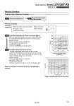
Load: F [N] Stroke [mm] 0 100 200 300 400 500 600 100 10 1 Force [N] Torque limit/Command value [%] 500 400 300 200 100 0 10 20 30 40 Lead 3: LEY25C Lead 6: LEY25B Lead 12: LEY25A Step 1 Check the pushing force. Mounting condition: Horizontal (pushing) Speed: 100 [mm/s] Jig weight: 0.5 [kg] Stroke: 300 [mm] Pushing force: 200 [N] Operating conditions Pushing Control Selection Procedure Selection Example Check the lateral load on the rod end. Step 1 Check the pushing force. Select the target model based on the torque limit/command value and pushing force with reference to the . Selection example) Based on the graph shown on the right side, Torque limit/Command value: 24 [%] Pushing force: 200 [N] Therefore, the LEY25B is temporarily selected. Step 2 Check the lateral load on the rod end. Confirm the allowable lateral load on the rod end of the actuator: LEY25B, which has been selected temporarily with reference to the . Selection example) Based on the graph shown on the right side, Jig weight: 0.2 [kg] . 2 [N] Product stroke: 200 [mm] Therefore, the lateral load on the rod end is in the allowable range. Step 2 Jig (LEY25) LEY32 LEY25 Based on the above calculation result, the LEY25B-300 is selected. Selection Procedure 185 Model Selection Series LEY/LEY-X5 Size 25, 32 Dust/Drip Proof (IP65) Specification