121-210-e-ley-en 60 / 104
10秒後にBOOKのページに移動します
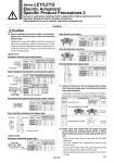
Handling Rod side Head side. Model LEY16 LEY25 LEY32/40 M4 x 0.7 M5 x 0.8 M6 x 1.0 1.5 3.0 5.2 Bolt 5.5 6.5 8.8 Max. tightening torque (N.m) Max. screw-in depth (mm) Model LEY16 LEY25 LEY32/40 M4 x 0.7 M5 x 0.8 M6 x 1.0 1.5 3.0 5.2 Bolt 7 8 10 Max. tightening torque (N.m) Max. screw-in depth (mm) Body fixed/Body bottom tapped style (When “Body bottom tapped” is selected.) Body fixed/Rod side/Head side tapped style Workpiece fixed/Plate tapped style Model LEYG16ML LEYG25ML LEYG 8 11 12 Max. screw-in depth (mm) 3.0 5.2 5.2 Max. tightening torque (N.m) M5 x 0.8 M6 x 1.0 M6 x 1.0 Bolt 32M 40L Body fixed/Bottom mounting Model LEYG16ML LEYG25ML LEYG 10 12 12 Max. screw-in depth (mm) 3.0 5.2 5.2 Max. tightening torque (N.m) M5 x 0.8 M6 x 1.0 M6 x 1.0 Bolt Body fixed/Head side tapped style Model LEYG16ML LEYG25ML LEYG 7 8 10 Max. screw-in depth (mm) 1.5 3.0 5.2 Max. tightening torque (N.m) M4 x 0.7 M5 x 0.8 M6 x 1.0 Bolt Tap (4 locations) Caution End socket End bracket screw-in depth Rod end nut Workpiece fixed/Rod end male thread (When “Rod end male thread” is selected.) Model LEY16 LEY25 LEY32/40 M8 x 1.25 M14 x 1.5 M14 x 1.5 12.5 65.0 65.0 Thread size 12 20.5 20.5 14 17 22 Max. tightening torque (N.m) Effective thread length (mm) End socket width across flats (mm) Model LEY16 LEY25 LEY32/40 5 or more 8 or more 8 or more End bracket screw-in depth (mm) 5 8 8 Length (mm) 13 22 22 Width across flats (mm) Rod end nut . Rod end nut is an accessary. . Except the LEYD. Workpiece fixed/Rod end female thread Model LEY16 LEY25 LEY32/40 M5 x 0.8 M8 x 1.25 M8 x 1.25 3.0 12.5 12.5 Bolt 10 13 13 14 17 22 Max. tightening torque (N.m) Max. screw-in depth (mm) End socket width across flats (mm)