121-210-e-ley-enü@ü@ü@50 / 104
10ĢbīŃé╔BOOKé╠āyü[āWé╔ł┌ō«éĄé▄éĘ
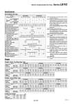
Specifications Weight Additional Weight Size Lock Motor cover Lock/Motor cover Lock unit specifications Model 30 11 66 to 130 5 to 125 15 5 37 to 72 9 to 250 35 or less 6 7 2 18 to 35 18 to 500 12 7.5 57 to 111 4 to 125 6 3.5 30 to 58 8 to 250 50 or less 3 1.5 16 to 30 15 to 500 30, 50, 100, 150, 200 30, 50, 100, 150, 200, 250, 300 3000 ü}0.02 0.1 or less 50/20 Ball screw + Belt (LEYG««), Ball screw (LEYG««D) Sliding bearing (LEYG«M), Ball bushing bearing (LEYG«L) 5 to 40 90 or less (No condensation) Pushing force [N] Note 3) 4) Speed [mm/s] Max. acceleration/deceleration [mm/s2] Pushing speed [mm/s] Note 5) Positioning repeatability [mm] Lost motion [mm] Note 6) Screw lead [mm] Impact/Vibration resistance [m/s2] Note 7) Actuation type Guide type Operating temp. range [üŗC] Operating humidity range [%RH] Motor size Motor output [W] Motor type Encoder Rated voltage [V] Power consumption [W] Note 8) Standby power consumption when operating [W] Note 9) Max. instantaneous power consumption [W] Note 10) Type Note 11) Holding force [N] Power consumption [W] Note 12) Rated voltage [V] Stroke [mm] Note 1) «28 30 «42 36 40 4 (Horizontal)/6 (Vertical) 59 86 4 (Horizontal)/12 (Vertical) 96 Servo motor (24 VDC) Incremental A/B (800 pulse/rotation)/Z phase 24 VDC ü}10% Non-magnetizing lock 24 VDC ü}10% 2.9 5 10 5 2.5 12 3 20 39 78 78 157 294 Electric specifications Actuator specifications Servo Motor (24 VDC) 30 0.83 0.83 50 0.97 0.97 100 1.20 1.20 150 1.49 1.49 200 1.66 1.66 30 1.66 1.62 50 1.85 1.81 100 2.17 2.13 150 2.59 2.55 200 2.93 2.89 250 3.27 3.23 300 3.53 3.49 30 2.90 . 50 3.16 . 100 3.71 . 150 4.27 . 200 4.94 . 250 5.43 . 300 5.87 . Model Step motor Servo motor LEYG16M LEYG25M LEYG32M Stroke [mm] Weight: In-line Motor Type Product weight [kg] 0.12 0.02 0.16 16 0.26 0.03 0.32 25 0.53 0.04 0.61 32 0.53 0.05 0.62 40 [kg] Work load [kg] Note 2) Horizontal Vertical Acceleration/Deceleration at 3000 [mm/s2] Acceleration/Deceleration at 3000 [mm/s2] Note 1) Consult with SMC for non-standard strokes as they are produced as special orders. Note 2) Horizontal: The maximum value of the work load for the positioning operation. The work load is the same as the vertical work load during pushing operation. An external guide is necessary to support the load. The actual work load and transfer speed change according to the condition of the external guide. Vertical: Check ügModel Selectionüh on page 164 for details. Set the acceleration/deceleration values to be 3000 [mm/s2] or less. Note 3) Pushing force accuracy is ü}20% (F.S.). Note 4) The pushing force values for LEYG16«A« is 50% to 95% and for LEYG25«A« is 50% to 95%. The pushing force values change according to the duty ratio and pushing speed. Check ügModel Selectionüh on page 165. Note 5) The allowable speed for the pushing operation. Note 6) A reference value for correcting an error in reciprocal operation. Note 7) Impact resistance: No malfunction occurred when it was tested with a drop tester in both an axial direction and a perpendicular direction to the lead screw. (Test was performed with the actuator in the initial state.) Vibration resistance: No malfunction occurred in a test ranging between 45 to 2000 Hz. Test was performed in both an axial direction and a perpendicular direction to the lead screw. (Test was performed with the actuator in the initial state.) Note 8) The power consumption (including the controller) is for when the actuator is operating. Note 9) The standby power consumption when operating (including the controller) is for when the actuator is stopped in the set position during the operation. Except during the pushing operation. Note 10) The maximum instantaneous power consumption (including the controller) is for when the actuator is operating. This value can be used for the selection of the power supply. Note 11) With lock only Note 12) For an actuator with lock, add the power consumption for the lock. LEYG16 A ML LEYG25 A ML 30 0.84 0.84 50 0.97 0.97 100 1.14 1.14 150 1.43 1.43 200 1.58 1.58 30 1.67 1.63 50 1.88 1.84 100 2.12 2.08 150 2.55 2.51 200 2.81 2.77 250 3.13 3.09 300 3.37 3.33 30 2.90 . 50 3.17 . 100 3.56 . 150 4.11 . 200 4.65 . 250 5.16 . 300 5.55 . Model Step motor Servo motor LEYG16L LEYG25L LEYG32L Stroke [mm] Product weight [kg] 30 0.83 0.83 50 0.97 0.97 100 1.20 1.20 150 1.49 1.49 200 1.66 1.66 30 1.67 1.63 50 1.86 1.82 100 2.18 2.14 150 2.60 2.56 200 2.94 2.90 250 3.28 3.24 300 3.54 3.50 30 2.91 . 50 3.17 . 100 3.72 . 150 4.28 . 200 4.95 . 250 5.44 . 300 5.88 . Model Step motor Servo motor LEYG16M LEYG25M LEYG32M Stroke [mm] Weight: Motor Top Mounting Type Product weight [kg] 30 0.84 0.84 50 0.97 0.97 100 1.14 1.14 150 1.43 1.43 200 1.58 1.58 30 1.68 1.64 50 1.89 1.85 100 2.13 2.09 150 2.56 2.52 200 2.82 2.78 250 3.14 3.10 300 3.38 3.34 30 2.91 . 50 3.18 . 100 3.57 . 150 4.12 . 200 4.66 . 250 5.17 . 300 5.56 . Model Step motor Servo motor LEYG16L LEYG25L LEYG32L Stroke [mm] Product weight [kg] 30 3.21 . 50 3.47 . 100 4.02 . 150 4.58 . 200 5.25 . 250 5.74 . 300 6.18 . 30 3.21 . 50 3.48 . 100 3.87 . 150 4.42 . 200 4.96 . 250 5.47 . 300 5.86 . Model Step motor Servo motor LEYG40M LEYG40L Stroke [mm] Product weight [kg] 30 3.20 . 50 3.46 . 100 4.01 . 150 4.57 . 200 5.24 . 250 5.73 . 300 6.17 . 30 3.20 . 50 3.47 . 100 3.86 . 150 4.41 . 200 4.95 . 250 5.46 . 300 5.85 . Model Step motor Servo motor LEYG40M LEYG40L Stroke [mm] Product weight [kg] 171 Electric Actuator/Guide Rod Type Series LEYG A