121-210-e-ley-en@@@49 / 104
10bÐèBOOKäy[WèÖÛçÉñ
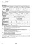
Specifications 4 6 1.5 14 to 38 15 to 500 11 17 3.5 27 to 74 8 to 250 20 30 7.5 51 to 141 4 to 125 12 18 7 63 to 122 18 to 500 30 50 15 126 to 238 9 to 250 3000 50 or less 35 or less 30 or less 30 or less 30 50 29 232 to 452 5 to 125 20 30 9 80 to 189 24 to 500 40 60 20 156 to 370 12 to 250 40 60 41 296 to 707 6 to 125 30, 50, 100, 150, 200 30, 50, 100, 150, 200, 250, 300 }0.02 0.1 or less 50/20 Ball screw + Belt (LEYGÞÛÞÛ), Ball screw (LEYGÞÛÞÛD) Sliding bearing (LEYGÞÛM), Ball bushing bearing (LEYGÞÛL) 5 to 40 90 or less (No condensation) 30, 50, 100, 150, 200, 250, 300 30 . 11 132 to 283 24 to 300 60 . 25 266 to 553 12 to 150 60 . 51 562 to 1058 6 to 75 30, 50, 100, 150, 200, 250, 300 Pushing force [N] Note 3) 4) 5) Speed [mm/s] Note 5) Max. acceleration/deceleration [mm/s2] Pushing speed [mm/s] Note 6) Positioning repeatability [mm] Lost motion [mm] Note 7) Screw lead [mm] Impact/Vibration resistance [m/s2] Note 8) Actuation type Guide type Operating temp. range [C] Operating humidity range [%RH] Motor size Motor type Encoder Rated voltage [V] Power consumption [W] Note 9) Standby power consumption when operating [W] Note 10) Max. instantaneous power consumption [W] Note 11) Type Note 12) Holding force [N] Power consumption [W] Note 13) Rated voltage [V] Work load [kg ] Note 2) Horizontal Vertical Acceleration/Deceleration at 3000 [mm/s2] Acceleration/Deceleration at 2000 [mm/s2] Acceleration/Deceleration at 3000 [mm/s2] ÞÛ28 ÞÛ42 Step motor (Servo/24 VDC) Incremental A/B phase (800 pulse/rotation) 24 VDC }10% ÞÛ56.4 ÞÛ56.4 10 5 2.5 12 6 3 16 8 23 16 43 40 15 48 Non-magnetizing lock 24 VDC }10% 50 48 104 50 48 106 2.9 5 5 4 16 8 4 20 39 78 78 157 294 108 216 421 5 127 265 519 Note 1) Consult with SMC for non-standard strokes as they are produced as special orders. Note 2) Horizontal: The maximum value of the work load for the positioning operation. The work load is the same as the vertical work load during pushing operation. An external guide is necessary to support the load. The actual work load and transfer speed change according to the condition of the external guide. Vertical: Speed changes according to the work load. Check gModel Selectionh on page 164. Set the acceleration/deceleration values to be 3000 [mm/s2] or less. Note 3) Pushing force accuracy is }20% (F.S.). Note 4) The pushing force values for LEYG16ÞÛÞÛ is 35% to 85%, for LEYG25ÞÛÞÛ is 35% to 65%, for LEYG32ÞÛÞÛ is 35% to 85% and for LEYG40ÞÛÞÛ is 35% to 65%. The pushing force values change according to the duty ratio and pushing speed. Check gModel Selectionh on page 165. Note 5) The speed and force may change depending on the cable length, load and mounting conditions. Furthermore, if the cable length exceeds 5 m, then it will decrease by up to 10% for each 5 m. (At 15 m: Reduced by up to 20%) When [M: Sliding bearing] is selected, the maximum speed of lead [A] is 400 mm/s (at no-load, horizontal mounting). The speed is also restricted with a horizontal/moment load. Refer to gModel Selectionh on page 162. Note 6) The allowable speed for the pushing operation. Note 7) A reference value for correcting an error in reciprocal operation. Note 8) Impact resistance: No malfunction occurred when it was tested with a drop tester in both an axial direction and a perpendicular direction to the lead screw. (Test was performed with the actuator in the initial state.) Vibration resistance: No malfunction occurred in a test ranging between 45 to 2000 Hz. Test was performed in both an axial direction and a perpendicular direction to the lead screw. (Test was performed with the actuator in the initial state.) Note 9) The power consumption (including the controller) is for when the actuator is operating. Note 10) The standby power consumption when operating (including the controller) is for when the actuator is stopped in the set position during the operation. Except during the pushing operation. Note 11) The maximum instantaneous power consumption (including the controller) is for when the actuator is operating. This value can be used for the selection of the power supply. Note 12) With lock only Note 13) For an actuator with lock, add the power consumption for the lock. Lock unit specifications Model Stroke [mm] Note 1) Electric specifications Actuator specifications Step Motor (Servo/24 VDC) LEYG16ML LEYG25ML LEYG32ML LEYG40ML 170 Series LEYG A