121-210-e-ley-en 42 / 104
10秒後にBOOKのページに移動します
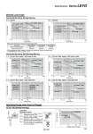
Transfer speed υ [m/min] Work load m [kg] 5 10 20 30 40 50 100 50 40 30 20 10 54 3 2 1 Stroke [mm] Load mass m [kg] Stroke [mm] Load mass m [kg] Stroke [mm] Load mass m [kg] Stroke [mm] Load mass m [kg] Stroke [mm] Load mass m [kg] Stroke [mm] Load mass m [kg] 0.1 1 10 10 35 40 100 1000 0.1 1 10 10 35 40 100 1000 0.1 1 10 0.1 1 10 10 35 40 100 1000 10 35 40 100 1000 0.1 1 10 0.1 1 10 10 70 75 100 1000 10 70 75 100 1000 LEYG32M𡱖/40M𡱖 LEYG16M𡱖 LEYG25M𡱖 LEYG32M𡱖/40M𡱖 LEYG16M𡱖 LEYG25M𡱖 LEYG16M𡱖 LEYG25M𡱖 LEYG32M𡱖/40M𡱖 LEYG16M𡱖 LEYG25M𡱖 LEYG32M𡱖/40M𡱖 LEYG16L𡱖 LEYG25L𡱖 LEYG32L𡱖/40L𡱖 LEYG16L𡱖 LEYG25L𡱖 LEYG32L𡱖/40L𡱖 LEYG16L𡱖 LEYG25L𡱖 LEYG32L𡱖/40L𡱖 LEYG16L𡱖 LEYG25L𡱖 LEYG32L𡱖/40L𡱖 LEYG16L𡱖 LEYG25L𡱖 LEYG32L𡱖/40L𡱖 LEYG16L𡱖 LEYG25L𡱖 LEYG32L𡱖/40L𡱖 LEYG16L𡱖 LEYG25L𡱖 LEYG32L𡱖/40L𡱖 LEYG16L𡱖 LEYG25L𡱖 LEYG32L𡱖/40L𡱖 120 125 120 125 120 125 120 125 LEYG𡱖M (Sliding bearing) L . 50 mm m υ Caution Operating Range when Used as Stopper Horizontal Mounting, Sliding Bearing t L = 50 mm Horizontal Mounting, Ball Bushing Bearing u L = 50 mm Max. speed = 200 mm/s or less Handling Precautions Note 1) When used as a stopper, select a model with 30 stroke or less. Note 2) LEYG𡱖L (ball bushing bearing) cannot be used as a stopper. Note 3) Workpiece collision in series with guide rod cannot be permitted (Fig. a). Note 4) The body should not be mounted on the end. It must be mounted on the top or bottom (Fig. b). . Set the speed to less than or equal to the values shown below. . For the specifications below, operate the system at the “load mass” shown in the graph x 80%. 𠌫 LEYG25MAA/Servo motor (24 VDC), Lead 12 Motor type LEYG𡱖M𡱖A Step motor (Servo/24 VDC) Servo motor (24 VDC) 200 mm/s 200 mm/s LEYG𡱖M𡱖B 125 mm/s 200 mm/s LEYG𡱖M𡱖C 75 mm/s 125 mm/s y L = 100 mm i L = 100 mm Max. speed = 200 mm/s or less o L = 50 mm Max. speed = Over 200 mm/s !0 L = 100 mm Max. speed = Over 200 mm/s LEYG32M/40M LEYG25M LEYG16M Moment Load Graph Fig. a Fig. b m 163 Model Selection Series LEYG