121-210-e-ley-en 39 / 104
10秒後にBOOKのページに移動します
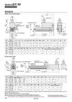
T M S M X W Q Y A + Stroke B + Stroke Rod operating range Note 1) Stroke GV EV FV OA J oOB (GH) FH EH M K Note 4) M oPB PC L oD 2 U Actuator cable H thread depth C PA [2] Origin Note 2) [Stroke end] Stroke end Note 3) [Origin] U Q A + Stroke B + Stroke W oPB Y PA Vent hole Note 5) Applicable tubing O.D. o4 Stroke L oD oOB FH EH M M G FV OA EV J K Note 4) H thread depth C [2] 2 Rod operating range Note 1) Origin Note 2) Stroke [Stroke end] end Note 3) [Origin] PC Vent hole Note 5) Applicable tubing O.D. o4 4 x O1 thread depth R 4 x O1 thread depth R 4 x O1 thread depth R Dimensions Motor top mounting type In-line motor type Note 1) Range within which the rod can move when it returns to origin. Make sure a workpiece mounted on the rod does not interfere with the workpieces and facilities around the rod. Note 2) Position after return to origin. Note 3) [ ] for when the direction of return to origin has changed. Note 4) The direction of rod end width across flats (K) differs depending on the products. Note 5) The vent hole is the port for releasing to atmosphere. Do not apply pressure to this hole. Attach tubing to the vent hole and place the end of the tubing so it is not exposed to dust or water. 196 201 146 151 15.3 15.3 0.9 1 28 28 9.3 9.3 15.6 15.6 38 38 37 37 8 10 M5 x 0.8 M6 x 1.0 34 40 Without lock With lock Q U PC W 24.5 26 M O1 R OA OB PA PB Y A B C D EH EV FH FV G H J K 15 to 100 101 to 400 20 to 100 101 to 500 Stroke range (mm) 15 to 100 101 to 400 20 to 100 101 to 500 Stroke range (mm) Size 25 32 R OA W X Size 25 32 OB PA PB Q S T U PC Without lock With lock Without lock With lock Stroke range (mm) 15 to 100 101 to 400 20 to 100 101 to 500 Stroke range (mm) Size 25 32 Size 25 32 34 40 14.5 18.5 17 22 24 31 M8 x 1.25 M8 x 1.25 139.5 173.5 65.6 75.6 56.8 78.6 57.6 69.6 45.5 56.5 44 51 20 25 13 13 116 141 130 160 130.5 155.5 148.5 178.5 M M5 x 0.8 M6 x 1.0 A B C D EH EV FH FV GH GV H J K L O1 1 1 Y 51 61 92 118 46 60 28 28 9.3 9.3 15.6 15.6 38 38 37 37 8 10 14.8 15.3 123 123 173 173 145 150 195 200 17 22 L 14.5 18.5 24 31 M8 x 1.25 M8 x 1.25 94.7 116.6 57.7 79.6 57.6 69.6 45.5 56.5 44 51 20 25 13 13 89.5 124.5 96 126 With lock 300 325 315.5 345.5 Without lock 250 275 265.5 295.5 15 to 100 101 to 400 20 to 100 101 to 500 For the rod end male thread, refer to page 148. For the mounting bracket dimensions, refer to page 152. 160 Series LEY-X5 Dust/Drip Proof (IP65) Specification