121-210-e-ley-en 36 / 104
10秒後にBOOKのページに移動します
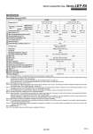
Specifications Model LEY25 LEY32 12 18 7 63 to 122 18 to 400 12 78 30 50 15 126 to 238 9 to 200 35 or less 6 42 40 15 48 157 5 30, 50, 100, 150, 200 250, 300, 350, 400 30, 50, 100, 150, 200 250, 300, 350, 400, 450, 500 30 50 29 232 to 452 5 to 100 3 294 3,000 ±0.02 0.1 or less 50/20 Sliding bushing (Piston rod) IP65 5 to 40 90 or less (No condensation) Step motor (Servo/24 VDC) Incremental A/B phase (800 pulse/rotation) 24 VDC ±10% Non-magnetizing lock 24 VDC ±10% Ball screw + Belt (LEY) Ball screw (LEYD) 20 30 10 80 to 189 24 to 400 16 108 40 60 21 156 to 370 12 to 200 30 or less 8 56.4 50 48 104 216 5 40 60 42 296 to 707 6 to 100 4 421 Pushing force [N] Note 3) Note 4) Note 5) Speed [mm/s] Note 5) Max. acceleration/deceleration [mm/s2] Pushing speed [mm/s] Note 6) Positioning repeatability [mm] Lost motion [mm] Note 7) Screw lead [mm] Impact/Vibration resistance [m/s2] Note 8) Actuation type Guide type Enclosure Operating temperature range [°C] Operating humidity range [%RH] Motor size Motor type Encoder Rated voltage [V] Power consumption [W] Note 9) Standby power consumption when operating [W] Note 10) Max. instantaneous power consumption [W] Note 11) Type Note 12) Holding force [N] Power consumption [W] Note 13) Rated voltage [V] Work load [kg] Note 2) Stroke [mm] Note 1) Horizontal Vertical (3000 [mm/s2]) (2000 [mm/s2]) (3000 [mm/s2]) Step Motor (Servo/24 VDC) Lock unit Electric specifications Actuator specifications specifications Note 1) Consult with SMC for non-standard strokes as they are produced as special orders. Note 2) Horizontal: The maximum value of the work load. An external guide is necessary to support the load. The actual work load and transfer speed change according to the condition of the external guide. Vertical: Speed changes according to the work load. Check “Model Selection” on page 138. The values shown in ( ) are the acceleration/deceleration. Set these values to be 3000 [mm/s2] or less. Note 3) Pushing force accuracy is ±20% (F.S.). Note 4) The pushing force values for LEY25 is 35% to 65% and for LEY32 is 35% to 85%. The pushing force values change according to the duty ratio and pushing speed. Check “Model Selection” on page 139. Note 5) The speed and force may change depending on the cable length, load and mounting conditions. Furthermore, if the cable length exceeds 5 m, then it will decrease by up to 10% for each 5 m. (At 15 m: Reduced by up to 20%) Note 6) The allowable speed for pushing operation. When push conveying a workpiece, operate at the vertical work load or less. Note 7) A reference value for correcting an error in reciprocal operation. Note 8) Impact resistance: No malfunction occurred when the actuator was tested with a drop tester in both an axial direction and a perpendicular direction to the lead screw. (Test was performed with the actuator in the initial state.) Vibration resistance: No malfunction occurred in a test ranging between 45 to 2000 Hz. Test was performed in both an axial direction and a perpendicular direction to the lead screw. (Test was performed with the actuator in the initial state.) Note 9) The power consumption (including the controller) is for when the actuator is operating. Note 10) The standby power consumption when operating (including the controller) is for when the actuator is stopped in the set position during the operation. Except during the pushing operation. Note 11) The maximum instantaneous power consumption (including the controller) is for when the actuator is operating. This value can be used for the selection of the power supply. Note 12) With lock only Note 13) For an actuator with lock, add the power consumption for the lock. 157 Electric Actuator/Rod Type Series LEY-X5 Dust/Drip Proof (IP65) Specification A