121-210-e-ley-en 23 / 104
10秒後にBOOKのページに移動します
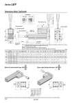
A + Stroke L B + Stroke Y X W EH EV J M M V K Note 4) H thread depth C 4 x O1 thread depth R S U T M M 4 x O1 thread depth R Motor cable (2 x o5) T2 U S1 U S1 T2 65 Cable length . 300 20 20 24 24 Step motor Servo motor Connector oD [2] 2 Origin Note 2) [Stroke end] Stroke end [Origin] Note 3) Rod operating range Note 1) Stroke Dimensions: Motor Top/Parallel Motor left side parallel type: LEY L 16 25 32 40 Motor right side parallel type: LEY R 16 25 32 40 Stroke range (mm) 10 to 100 101 to 300 15 to 100 101 to 400 20 to 100 101 to 500 20 to 100 101 to 500 101 121 130.5 155.5 148.5 178.5 148.5 178.5 90.5 110.5 116 141 130 160 130 160 10 13 13 13 Size [mm] 16 25 32 40 A B C 16 20 25 25 D 34 44 51 51 EH 34.3 45.5 56.5 56.5 EV M5 x 0.8 M8 x 1.25 M8 x 1.25 M8 x 1.25 H 18 24 31 31 J 14 17 22 22 K 10.5 14.5 18.5 18.5 L 25.5 34 40 40 M O1 7 8 10 10 R 35 46 60 60 S 67.5 92 118 118 T 0.5 1 1 1 U 28 42 56.4 56.4 V 61.8 63.4 68.4 90.4 W 80.3 85.4 95.4 117.4 X 62.5 59.6 . . W 81 81.6 . . X 22.5 26.5 34 34 Y M4 x 0.7 M5 x 0.8 M6 x 1.0 M6 x 1.0 35.5 47 61 67 91 117 Size 16 25 32, 40 S1 T2 0.5 1 1 U [mm] Step motor Servo motor Note) When the motor is mounted on the left or right side in parallel, the groove for auto switch on the side to which the motor is mounted is hidden. Note 1) Range within which the rod can move when it returns to origin. Make sure a workpiece mounted on the rod does not interfere with the workpieces and facilities around the rod. Note 2) Position after return to origin. Note 3) [ ] for when the direction of return to origin has changed. Note 4) The direction of rod end width across flats (K) differs depending on the products. Series LEY 146