121-210-e-ley-enĀ@Ā@Ā@14 / 104
10ēbĆ„ā…BOOKāŐÉyĀ[ÉWā…ąŕďģāĶā‹ā∑
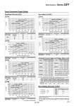
Force [N] Force [N] Set value of pushing force [%]. Set value of pushing force [%]. Force [N] Set value of pushing force [%]. Force [N] . Set values for the controller. Force Conversion Graph (Guide) Non-rotating Accuracy of Rod Step Motor (Servo/24 VDC) LEY16 LEY25 LEY32 Set value of pushing force [%] Duty ratio [%] Continuous pushing time [minute] 65 or less 100 . Ambient temperature 40ĀčC or less Set value of pushing force [%] Duty ratio [%] Continuous pushing time [minute] 65 or less 100 . Ambient temperature 40ĀčC or less Ambient temperature Set value of pushing force [%] Duty ratio [%] Continuous pushing time [minute] 85 or less 40 or less 50 70 85 25ĀčC or less 40ĀčC 100 100 70 20 15 . . 12 1.3 0.8 Lead 2.5: LEY16C Lead 5: LEY16B Lead 10: LEY16A Lead 3: LEY25C Lead 6: LEY25B Lead 12: LEY25A Lead 4: LEY32C Lead 8: LEY32B Lead 16: LEY32A 0 20 40 60 80 100 120 140 160 10 20 30 40 50 60 70 80 90 10 20 30 40 50 60 70 80 90 10 20 30 40 50 60 70 80 90 Set value of pushing force [%]. Max. 85% Max. 85% 0 100 200 300 400 500 Max. 65% 0 100 200 300 400 500 600 700 800 LEY40 Set value of pushing force [%] Duty ratio [%] Continuous pushing time [minute] 85 or less 65 or less 85 100 100 50 . . 15 Ambient temperature 25ĀčC or less 40ĀčC Lead 4: LEY40C Lead 8: LEY40B Lead 16: LEY40A 10 20 30 40 50 60 70 80 90 0 100 200 300 400 500 600 700 1100 800 900 1000 Force [N] Set value of pushing force [%]. Set value of pushing force [%]. Force [N] Max. 95% Max. 95% Servo Motor (24 VDC) LEY16 LEY25 Set value of pushing force [%] Duty ratio [%] Continuous pushing time [minute] 95 or less 100 . Ambient temperature 40ĀčC or less Set value of pushing force [%] Duty ratio [%] Continuous pushing time [minute] 95 or less 100 . Ambient temperature 40ĀčC or less Model Pushing speed [mm/s] Pushing force (Setting input value) 1 to 4 5 to 20 21 to 50 1 to 4 5 to 20 21 to 35 1 to 4 5 to 20 21 to 30 1 to 4 5 to 20 21 to 30 30% to 85% 35% to 85% 60% to 85% 20% to 65% 35% to 65% 50% to 65% 20% to 85% 35% to 85% 60% to 85% 20% to 65% 35% to 65% 50% to 65% LEY16ūģ LEY25ūģ LEY32ūģ LEY40ūģ