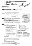
T1 a1 a2 L Speed: V [mm/s] Time [s] T2 T3 T4 Work load [kg] Speed [mm/s] 10 8 6 4 2 0 0 100 200 300 400 500 600 Step 1 Check the work load.speed. Step 2 Check the cycle time. ūźWorkpiece mass: 4 [kg] ūźSpeed: 100 [mm/s] ūźAcceleration/Deceleration: 3,000 [mm/s2] ūźStroke: 200 [mm] ūźWorkpiece mounting condition: Vertical upward downward transfer Operating conditions Selection Procedure Positioning Control Selection Procedure Selection Example Step 1 Check the work load.speed. (Vertical transfer) Step 2 Check the cycle time. Calculate the cycle time using the following calculation method. ūźCycle time T can be found from the following equation. Select the target model based on the workpiece mass and speed with reference to the . Selection example) The LEY16B is temporarily selected based on the graph shown on the right side. T = T1 + T2 + T3 + T4 [s] T1 = V/a1 [s] T4 = 0.2 [s] T3 = V/a2 [s] T2 = [s] L . 0.5 ĀE V ĀE (T1 + T3) V ūźT4: Settling time varies depending on the conditions such as motor types, load and in positioning of the step data. Therefore, please calculate the settling time with reference to the following value. ūźT2: Constant speed time can be found from the following equation. ūźT1: Acceleration time and T3: Deceleration time can be obtained by the following equation. L : Stroke [mm] ... (Operating condition) V : Speed [mm/s] ... (Operating condition) a1: Acceleration [mm/s2] ... (Operating condition) a2: Deceleration [mm/s2] ... (Operating condition) T1: Acceleration time [s] ... Time until reaching the set speed T2: Constant speed time [s] ... Time while the actuator is operating at a constant speed T3: Deceleration time [s] ... Time from the beginning of the constant speed operation to stop Calculation example) T4: Settling time [s] ... Time until in position is completed T1 to T4 can be calculated as follows. T1 = V/a1 = 100/3000 = 0.033 [s], T3 = V/a2 = 100/3000 = 0.033 [s] T4 = 0.2 [s] Therefore, the cycle time can be obtained as follows. T = T1 + T2 + T3 + T4 = 0.033 + 1.967 + 0.033 + 0.2 = 2.233 [s] T2 = = = 1.97 [s] L . 0.5 ĀE V ĀE (T1 + T3) V 200 . 0.5 ĀE 100 ĀE (0.033 + 0.033) 100 W (LEY16/Step motor) Lead 5: LEY16B Lead 10: LEY16A Lead 2.5: LEY16C Based on the above calculation result, the LEY16B-200 is selected. Electric Actuator/Rod Type Series LEY Model Selection Step Motor (Servo/24 VDC) Servo Motor (24 VDC) . It is necessary to mount a guide outside the actuator when used for horizontal transfer. When selecting the target model, refer to page 142 for the horizontal work load in the specifications, and page 179 for the precautions. 134