7-p1423-1439-hed_enü@ü@ü@8 / 18
10ĢbīŃé╔BOOKé╠āyü[āWé╔ł┌ō«éĄé▄éĘ
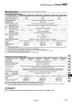
Main Specifications (For details, please consult our ügProduct Specificationsüh information.) Note 1) The conditions are as follows. Circulating fluid: Water (Circulating flow rate 15 L/min, Set temperature 25üŗC), Facility water temperature 25üŗC, Facility water flow rate 5 L/min, Ambient temperature 25üŗC Note 2) For the compatibility between the circulating fluid and materials, refer to ügApplicable Fluidsüh. Note that the Chemical Thermo-con is not designed to be explosion proof so it is not suitable for flammable fluids. Note 3) Install the heat exchanger in the discharge side of a circulating pump. Do not use at location where a negative pressure is applied. The circulating fluid pump should be prepared by the customer. Note 4) The outline dimensions do not included protruding parts such as the foot flange and tube. HED003-HW13 HED003-HW19 HED005-HW13 HED005-HW19 HED007-HW13 HED007-HW19 300 W 600 W 750 W 1800 W Heat exchanger model Applicable fluid Note 2) Wetted parts material Operating pressure Note 3) Tube size (PFA tube) Temperature Wetted parts material Max. operating pressure Tube size Flow rate 500 W 1000 W Peltier device (Thermoelectric device, Thermo-module) Water-cooled 10.0 to 60.0üŗC (depending on the type of circulating fluid) Deionized water, Hydrofluoric acid, Ammonia hydrogen peroxide solution, etc. PFA 0 (atmospheric pressure) to 0.35 MPa 10 to 35üŗC (no condensation) FEP, Stainless steel 304, Stainless steel 316 0.5 MPa IN/OUT: FEP tube 3/8" x 1/4" 5 to 10 L/min Temperature: 10 to 35üŗC, Humidity: 35 to 80%RH (no condensation) 1/2" x 3/8" W130 mm x D263 mm x H170 mm Approx. 8 kg HED003-C2A HED003-C2B HED005-C2A HED005-C2B HED007-C2A HED007-C2B HED003-HW13 HED003-HW19 HED005-HW13 HED005-HW19 HED007-HW13 HED007-HW19 W150 mm x D294 mm x H222 mm Approx. 15 kg 3/4" x 5/8" 1/2" x 3/8" 3/4" x 5/8" 1/2" x 3/8" 3/4" x 5/8" Heat Exchanger Specifications Note 1) This value is with a stable load with no disturbance and cannot be achieved in some operating conditions. Note 2) The outline dimensions do not included protruding parts such as the foot flange, screw and connector. Note 3) The temperature controller should be connected with a specific series of heat exchanger. If connected with a different series of heat exchanger, it may not operate normally. (The HED003 and HED005 series use the same connector, so be careful for incorrect wiring.) HED003-C2A RS-485 HED003-C2B RS-232C HED005-C2A RS-485 HED005-C2B RS-232C HED007-C2A RS-485 HED007-C2B Communication RS-232C Control method Operating temperature range Temperature stability Note 1) Temperature sensor Main functions Ambient temperature/humidity Temperature controller model Power supply Rated current Cooling/Heating automatic shift PID control 10.0 to 60.0üŗC (no condensation) Within ü}0.1üŗC (with stable load) Resistance thermometer Pt100 āČ, 3-wires, class A, 2 mA (for both internal control sensor and external sensor) The external sensor should be prepared by the customer. Auto-tuning, Sensor fine adjustment, Offset, Learning control, External sensor control, Set value memory, Upper/Lower temperature limit alarm, Output shutdown alarm, Remote ON/OFF, Leakage detection Temperature: 10 to 35üŗC, Humidity: 35 to 80%RH (no condensation) Single-phase 180 to 242 VAC 50/60 Hz 5 A W140 mm x D350 mm x H215 mm Approx. 8 kg 3 A W100 mm x D320 mm x H215 mm Approx. 6 kg 14 A W165 mm x D447 mm x H215 mm Approx. 13 kg Temperature Controller Specifications Caution æ For the combination of the heat exchanger and temperature controller, refer to ügCombination in Setüh. Cooling capacity (Water) Note 1) Heating capacity (Water) Note 1) Cooling/Heating method Radiating method Operating temperature range Ambient temperature/humidity Dimensions Note 4) Weight Circulating fluid Facility water Applied temperature controller W150 mm x D294 mm x H222 mm Approx. 14 kg Applied heat exchanger Dimensions Note 2) Weight Power supply spec. Note 3) Chemical Thermo-con Series HED 1429 HRG HRS HRZ HRZD HRW HEC HEB HED HEA IDH