7-p1423-1439-hed_en 14 / 18
10秒後にBOOKのページに移動します
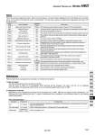
Alarm This unit has failure diagnosis function. When an failure happens, its failure mode is displayed on the LCD display in the controller and it can be read out through the serial communication, and has relay outputs for upper/lower temperature limit alarm and shutdown alarm. Please prepare back-up equipment as necessary to minimize the downtime. Maintenance 1) Heat exchanger The heat exchanger will not be repaired in principle. Only the return to SMC for an investigation within warranty will be accepted. The return unit has to be completely decontaminated with appropriate method such as use of neutralizing agent before return to SMC. 2) Temperature controller Maintenance of the temperature controller will be performed only at SMC. SMC will not support on-site maintenance. The following parts have published life time. To make a maintenance return schedule is recommended based on the following parts life expectation. Parts Life Expectation Alarm code Alarm description Operation status Main reason WRN WRN ERR00 ERR01 ERR03 ERR04 ERR05 ERR11 ERR12 ERR13 ERR14 ERR15 ERR17 ERR18 ERR19 ERR21 ERR22 Upper/Lower temp. limit alarm Remote OFF alarm CPU hung-up CPU check failure Back-up data error EEPROM writing error EEPROM input over time error DC power voltage failure Internal sensor value is high. Internal sensor value is low. Thermostat alarm Output failure alarm Cutoff/short of internal sensor Cutoff/short of external sensor Auto-tuning failure Fan alarm Leak alarm Continue Stop Stop Stop Stop Stop Stop Stop Stop Stop Stop Continue Stop Stop Stop Stop Continued by normal control The temperature has exceeded the upper or lower limit of the set temperature. The remote ON/OFF contact is set to be off. (This alarm is not generated by the relay output.) The CPU has crashed due to noise, etc. The contents of the CPU cannot be read out correctly when the power supply is turned on. The data cannot be written to EEPROM. The number of times of writing to EEPROM has exceeded the maximum value. The internal temperature sensor has been disconnected or short-circuited. Auto-tuning has not been completed within 60 minutes. The air-cooled fan alarm of the power supply has been activated. The fluid leak sensor has detected leakage of fluid. The contents of the back-up data cannot be read out correctly when the power supply is turned on. Momentary loss of AC power supply, DC power supply has excessive temperature, or the thermo-module has been short-circuited. The internal temperature sensor has exceeded the upper limit where the Chemical Thermo-con is set to stop. The internal temperature sensor has exceeded the lower limit where the Chemical Thermo-con is set to stop. The temperature cannot be changed even at 100% output, due to overload or disconnection of the thermo-module. The thermostat has been activated due to insufficient flow rate of the circulating fluid or facility water or high temperature. The external temperature sensor has been disconnected or short-circuited. (Only detected when in learning control, auto-tuning operation 2, or external sensor control) Description Expected life 5 to 10 years 5 to 10 years Fan DC power supply Display panel 50,000 hours (approx. 5 years) Possible failure Lack of fan cooling because of the life time of the bearing. It will activate the overheat protection of DC power supply and generate alarm. End life of electrolytic condenser. It will generate DC power supply alarm. End life of backlight of LCD. Chemical Thermo-con Series HED 1435 HRG HRS HRZ HRZD HRW HEC HEB HED HEA IDH