7-p1379-1411-hec_en 4 / 34
10秒後にBOOKのページに移動します
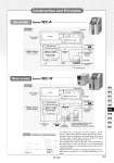
The Thermo-con is constructed as shown in Figure 1. It interposes a Peltier device (thermo-module) between the heat exchangers for the circulating fluid and facility water and controls the pulse width of supply direct current to achieve the target outlet temperature of circulating fluid precisely. The circulating fluid returns to the tank, and is transferred by the pump which is built in the Thermo-con, and goes through the heat exchangers and internal sensors and out from the circulating fluid outlet. Figure 2 shows an example of circulating fluid piping. The circulating fluid is transferred at a constant temperature by the pump. Figure 2 Flow switch (option) Noise filter Circulating fluid supply port (Tank lid) Circulating fluid Level switch Tank Temperature sensor Pump Peltier device (Thermo-module) Fan T Power switch PE Power supply & Controller Circulating fluid drain port Fan Switching power supply Controller Circulating fluid OUT IN Target of temperature Thermo-con control Example of circulating fluid piping Figure 1 Heat exchanger (Circulating fluid side) Heat exchanger (Cooling side) Figure 1 T Noise filter Power switch PE Power supply & Controller Fan Switching power supply Controller Pump Circulating fluid Peltier device (Thermo-module) Circulating fluid OUT IN Heat exchanger (Circulating fluid side) Heat exchanger (Cooling side) Circulating .2 tank Supply tank Level switch .1 Facility water Facility water IN OUT Temperature sensor Circulating fluid supply port (Tank lid) Circulating fluid drain port Flow switch .3 *1 Optional setting for the HEC001 and 003 *2 Not built in the HEC001 and 003 *3 Optional setting for the HEC001 and 003 only Water-cooled Air-cooled Series HEC-A Series HEC-W Construction and Principles 1381 HRG HRS HRZ HRZD HRW HEC HEB HED HEA IDH