7-p1313-1346-hrz_en 13 / 35
10秒後にBOOKのページに移動します
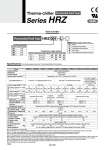
Thermo-chiller Series HRZ Fluorinated Fluid Type R SEMI Specifications (For details, please consult our “Product Specifications” information.) How to Order Fluorinated Fluid Type HRZ 001 L Cooling capacity Symbol 001 002 004 008 Cooling capacity 1 kW 2 kW 4 kW 8 kW Temperature range setting .20 to 40°C 20 to 90°C .20 to 90°C 1 kW 傱傱 . 2 kW 傱傱傱 4 kW 傱傱 . 8 kW 傱傱傱 Symbol L H W Temperature range setting None Analog communication DeviceNet communication NPT fitting Circulating fluid automatic recovery Nil C D N Z Option (Refer to pages 1342 and 1343.) Note 1) It should have no condensation. Note 2) Fluorinert. is a trademark of 3M and GALDENR is a registered trademark of Solvay Solexis, Inc. Regarding the fluid other than the above, please contact SMC. Note 3) q Facility water temperature: 25°C, w Circulating fluid flow rate: Values at rated circulating fluid flow rate. Values common for 50/60 Hz. Note 4) Value with a stable load without turbulence in the operating conditions. It may be out of this range depending on operating conditions. Note 5) The capacity at the Thermo-chiller outlet when the circulating fluid temperature is 20°C. Note 6) Required flow rate for cooling capacity or maintaining the temperature stability. When used below the rated flow, use the individually sold, “By-pass Piping Set” (Refer to page 1339). Note 7) Minimum volume required for operating only the Thermo-chiller. (Circulating fluid temperature: 20°C, including the Thermo-chiller’s internal pipings or heat exchanger) Note 8) Preliminary space volume without main tank capacity. Available for collecting the circulating fluid inside an external piping or for preliminary injection. Note 9) Required flow rate when a load for the cooling capacity is applied at a facility water temperature of 25°C. Note 10) Weight in the dry state without circulating fluids Model HRZ001-L Cooling method Refrigerant Control system Ambient temp./humidity Note 1) Circulating fluid Note 2) Temp. range setting Note 1) (°C) Cooling capacity Note 3) (kW) Heating capacity Note 3) (kW) Temp. stability Note 4) (°C) Rated flow Note 6) (L/min) Main tank capacity Note 7) (L) Sub-tank capacity Note 8) (L) Port size Wetted parts material Temperature range (°C) Pressure range (MPa) Required flow rate Note 9) (50/60 Hz) (L/min) Port size Wetted parts material Power supply Breaker capacity (A) Rated current (A) Alarm Communications Pump capacity Note 5) (50/60 Hz) (MPa) Weight Note 10) (kg) Safety standards HRZ002-L HRZ004-L HRZ008-L HRZ001-H HRZ002-H HRZ004-H HRZ008-H HRZ002-W HRZ008-W Water-cooled refrigeration R404A (HFC) PID control Temperature: 10 to 35°C, Humidity: 30 to 70%RH 20 Approx. 15 Approx. 16 30 Approx. 22 Approx. 17 20 Approx. 12 Approx. 15 Rc3/4 Stainless steel, EPDM, Copper brazing (Heat exchanger), PPS, Silicone, Fluororesin 10 to 25 0.3 to 0.7 Rc1/2 Stainless steel, EPDM, Copper brazing (Heat exchanger), Silicone, Brass 3-phase 200 VAC 50 Hz, 3-phase 200 to 208 VAC 60 Hz Allowable voltage fluctuation ±10% Refer to page 1338. Contact input/output (D-sub 25 pin) and Serial RS-485 (D-sub 9 pin) (Refer to pages 1336 and 1337.) UL, CE marking, SEMI (S2-0703, S8-0701, F47-0200), SEMATECH (S2-93, S8-95) 30 20 25 60 46 170 175 275 145 170 20 14 30 23 5/5 6/6 15/22 18/23 3/4 5/6 9/10 13/14 6/7 13/14 Approx. 15 Approx. 16 ±0.1 .20 to 40 20 to 90 .20 to 90 1.0 (at .10°C) 0.45/0.65 (at 20 L/min) 0.65/0.95 0.45/0.65 (at 20 L/min) (at 30 L/min) 0.40/0.60 (at 20 L/min) Fluorinert. FC-3283/GALDENR HT135 Fluorinert. FC-40/GALDENR HT200 . .20 to 40°C: Fluorinert. FC-3283/GALDENR HT135 . 20 to 90°C: Fluorinert. FC-40/GALDENR HT200 2.0 (at .10°C) 1.0 (at 20°C) 2.0 (at 20°C) 4.0 (at 20°C) 8.0 (at 20°C) 2.0 (at 20°C) 8.0 (at 20°C) 4.0 (at .10°C) 8.0 (at .10°C) 2.8 (at .10°C) 3.2 (at .10°C) 2.3 (at 20°C) 2.6 (at 20°C) 2.8 (at 20°C) 3.0 (at 20°C) 2.3 (at 20°C) 3.3 (at 20°C) 3.6 (at .10°C) 5.9 (at .10°C) Electrical system Cooling water system Circulating fluid system 1324