7-p1283-1312-hrs_en 7 / 31
10秒後にBOOKのページに移動します
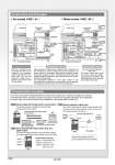
Circulating fluid circuit Refrigeration circuit Pressure sensor (For high-pressure refrigerant gas) Expansion valve A Expansion valve B Pressure sensor (For discharge) Temperature sensor (For discharge) Circulating fluid outlet Rc1/2 傜 Water-cooled HRS尰-W-尰 Air-cooled condenser Filter Ventilation PC HRS Remote operation switch Output 1 Output 2 Output 3 Input 1 Input 2 To the customer’s machine HRS HRS Drain port Plug Circulating fluid circuit Refrigeration circuit Resin tank Level switch Pressure sensor (For high-pressure refrigerant gas) Expansion valve A Expansion valve B Temperature sensor (For compressor intake) Temperature sensor (For return) Pressure sensor (For discharge) Temperature sensor (For discharge) Circulating fluid return port Rc1/2 Evaporator Circulating fluid outlet Rc1/2 Pressure sensor (For low-pressure Compressor refrigerant gas) Comp Filter Drain port Pump Facility water outlet Rc3/8 Facility water inlet Rc3/8 Water control Facility water valve circuit Water-cooled condenser Resin tank Level switch Temperature sensor (For compressor intake) Temperature sensor (For return) Circulating fluid return port Rc1/2 Evaporator 傜 Air-cooled HRS尰-A-尰 Pressure sensor (For low-pressure refrigerant gas) Compressor Comp Pump With the circulating pump, circulating fluid will be discharged to the customer’s machine side. After the circulating fluid will cool the customer’s machine side, it will heat up and return to the Thermo-chiller. High-temperature, high-pressure refrigerant gas compressed by the compressor is made to release heat by the condenser, and turns to liquid. As the liquefied high-pressure refrigerant passes through the expansion valve A, it expands and cools down; as it passes through the evaporator, heat is extracted from the circulating fluid and it evaporates. The evaporated refrigerant is once again sucked in and compressed by the compressor, and the above cycle is repeated. The expansion valve B is open to heat the circulating fluid. Circulating fluid circuit Refrigeration circuit Facility water circuit Communication Function The serial communication (RS232C/RS485) and contact I/Os (2 inputs and 3 outputs) are equipped as standard. Communication with the customer’s machine and system construction are possible, depending on the application. A 24 VDC output can be also provided, and is available for a flow switch (SMC’s PF2W, etc.). Remote signal I/O through serial communication The remote operation is enabled (to start and stop) through serial communication. Alarm and operation status (start, stop, etc.) signal output The alarm and status generated in the product are assigned to 3 output signals based on their contents, and can be output. Remote operation signal input One of the contact inputs is used for remote operation and the other is used for a flow switch to monitor the flow, and their warning outputs are taken in. Flow switch Low flow switch flow signal . Output setting example Output 1: Temperature rise Output 2: Pressure rise Output 3: Operation status (start, stop, etc.) Ex. 1 傱 Circulating fluid temperature setting 傱 Start and stop 傱 Circulating fluid discharge temperature 傱 Circulating fluid discharge pressure 傱 Run and stop status 傱 Alarm information 傱 Various setting information 傱 Preparation completion status For water-cooled refrigeration HRS尰-W-尰 The water control valve opens and closes to keep the refrigerant gas pressure consistent. The facility water flow rate is controlled by the water control valve. Power for flow switch (24 VDC) can be supplied from thermo-chiller. Construction and Principles Ex. 3 Ex. 2 1288