7-p1283-1312-hrs_en 27 / 31
10秒後にBOOKのページに移動します
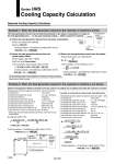
P Q: Heat generation amount Customer’s machine I: Current V: Power supply voltage Power consumption Thermo-chiller T2: Return temperature qv: Circulating fluid flow rate Q: Heat generation amount Customer’s machine T = T2 . T1 T1: Outlet temperature Example 1: When the heat generation amount in the customer’s machine is known. Required Cooling Capacity Calculation Example 2: When the heat generation amount in the customer’s machine is not known. Series HRS Cooling Capacity Calculation (1) Derive the heat generation amount from the power consumption. Power consumption P: 1000 [W] Q = P = 1000 [W] Cooling capacity = Considering a safety factor of 20%, 1000 [W] x 1.2 = 1200 [W] (2) Derive the heat generation amount from the power supply output. Power supply output VI: 1.0 [kVA] Q = P = V x I x Power factor In this example, using a power factor of 0.85: = 1.0 [kVA] x 0.85 = 0.85 [kW] = 850 [W] Cooling capacity = Considering a safety factor of 20%, 850 [W] x 1.2 = 1020 [W] The heat generation amount can be determined based on the power consumption or output of the heat generating area . i.e. the area requiring cooling . within customer’s machine.. . The above examples calculate the heat generation amount based on the power consumption. The actual heat generation amount may differ due to the structure of customer’s machine. Please be sure to check it carefully. (3) Derive the heat generation amount from the output. Output (shaft power, etc.) W: 800 [W] Q = P = In this example, use an efficiency of 0.7: = = 1143 [W] Cooling capacity = Considering a safety factor of 20%, 1143 [W] x 1.2 = 1372 [W] W Efficiency 800 0.7 Obtain the temperature difference between inlet and outlet by circulating the circulating fluid inside the customer’s machine. Q = qm x C x (T2 . T1) ρ x qv x C x T 60 = 1 x 10 x 4.2 x 103 x 2.0 60 = = 1400 [J/s] .1400 [W] Cooling capacity = Considering a safety factor of 20%, 1400 [W] x 1.2 = 1680 [W] Heat generation amount by customer’s machine Q Circulating fluid Circulating fluid weight flow rate qm Circulating fluid density ρ Circulating fluid (volume) flow rate qv Circulating fluid specific heat capacity C Circulating fluid outlet temperature T1 Circulating fluid return temperature T2 Circulating fluid temperature difference T Conversion factor: minutes to seconds (SI units) . Refer to page 1309 for the typical physical property value of clear water or other circulating fluids. : Unknown [W] ([J/s]) : Clear water. : (= ρ x qv ÷ 60) [kg/s] : 1 [kg/dm3] : 10 [dm3/min] : 4.2 x 10³ [J/(kg・K)] : 293 [K] (20 [°C]) : 295 [K] (22 [°C]) : 2.0 [K] (= T2 . T1) : 60 [s/min] Heat generation amount by customer’s machine Q Circulating fluid Circulating fluid weight flow rate qm Circulating fluid weight volume ratio γ Circulating fluid (volume) flow rate qv Circulating fluid specific heat capacity C Circulating fluid outlet temperature T1 Circulating fluid return temperature T2 Circulating fluid temperature difference T Conversion factor: hours to minutes Conversion factor: kcal/h to kW : Unknown [cal/h] → [W] : Clear water. : (= ρ x qv x 60) [kgf/h] : 1 [kgf/L] : 10 [L/min] : 1.0 x 10³ [cal/(kgf・°C)] : 20 [°C] : 22 [°C] : 2.0 [°C] (= T2 . T1) : 60 [min/h] : 860 [(cal/h)/W] Example of conventional measurement units (Reference) Cooling capacity = Considering a safety factor of 20%, 1400 [W] x 1.2 = 1680 [W] Q = qm x C x (T2 . T1) 860 1200000 [cal/h] 860 .1400 [W] = 1 x 10 x 60 x 1.0 x 103 x 2.0 860 = γ x qv x 60 x C x T 860 = 1308