7-p1283-1312-hrs_enĀ@Ā@Ā@16 / 31
10ēbĆ„ā…BOOKāŐÉyĀ[ÉWā…ąŕďģāĶā‹ā∑
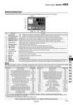
ew q t r y u i o !0!5 !1 !2 !3!6 !4 Operation Display Panel The basic operation of this unit is controlled through the operation display panel on the front of the product. q w e r t y u i o !0 !1 !2 !3 !4 !5 !6 Digital display (7-segment and 4 digits) [ĀčC] [ĀčF] indicator [MPa] [PSI] indicator [REMOTE] indicator [RUN] indicator [ALARM] indicator [ ] indicator [ ] indicator [ ] indicator [RUN/STOP] key [MENU] key [SEL] key [ūČ] key [ūą] key [PUMP] key [RESET] key Equipped with a unit conversion function. Displays the unit of display temperature (default setting: ĀčC). Equipped with a unit conversion function. Displays the unit of display pressure (default setting: MPa). Enables remote operation (start and stop) by communication. Lights up during remote operation. Lights up when the product is started, and goes off when it is stopped. Flashes during stand-by for stop or anti-freezing function, or independent operation of the pump. Flashes with buzzer when alarm occurs. Lights up when the surface of the fluid level indicator falls below the L level. Equipped with a timer for start and stop. Lights up when this function is operated. Equipped with a power failure auto-restart function, which restarts the product automatically after stopped due to a power failure, is provided. Lights up when this function is operated. Makes the product start or stop. Changes the item in menu and enters the set value. Decreases the set value. Increases the set value. Press the [MENU] and [RUN/STOP] keys simultaneously. The pump starts running independently to make the product ready for start-up (release the air). Press the [ūČ] and [ūą] keys simultaneously. The alarm buzzer is stopped and the [ALARM] indicator is reset. Shifts the main menu (display screen of circulating fluid discharge temperature and pressure) and other menus (for monitoring and entry of set values). Displays the circulating fluid current discharge temperature and pressure and alarm codes and other menu items (codes). Displays the circulating fluid discharge temperature and the set values of other menus. No. Description Function PV SV Alarm This unit has 35 types of alarms as standard, and displays each of them by its alarm code on the PV screen with the [ALARM] lamp ([LOW LEVEL] lamp) lit up on the operation display panel. The alarm can be read out through communication. .1 ĀgStopĀh or ĀgContinueĀh are default settings. Customers can change them to ĀgContinueĀh and ĀgStopĀh. For details, read the Operation Manual. .2 ĀgAL19, AL31, AL32Āh are disabled in the default setting. If this function is necessary, it should be set by the customer referring to the Operation Manual. .3 For water-cooled models, the alarm is not activated. .4 This alarm function can be used when the option (sold separately) is used. Please download the Operation Manual via our website. http://www.smcworld.com Alarm code AL01 AL02 AL03 AL04 AL05 AL06 AL07 AL08 AL09 AL10 AL11 AL12 AL13 AL15 AL16 AL17 AL18 AL19 .2 Alarm message Low level in tank High circulating fluid discharge temperature Circulating fluid discharge temperature rise Circulating fluid discharge temperature drop High circulating fluid return temperature (60ĀčC) High circulating fluid discharge pressure Abnormal pump operation Circulating fluid discharge pressure rise Circulating fluid discharge pressure drop High compressor intake temperature Low compressor intake temperature Low super heat temperature High compressor discharge pressure Refrigerating circuit pressure (high pressure side) drop Refrigerating circuit pressure (low pressure side) rise Refrigerating circuit pressure (low pressure side) drop Compressor overload Communication error .2 Stop .1 Stop Continue .1 Continue .1 Stop Stop Stop Continue .1 Continue .1 Stop Stop Stop Stop Stop Stop Stop Stop Continue .1 Operation status Alarm code AL20 AL21 AL22 AL23 AL24 AL25 AL26 AL27 AL28 AL29 AL30 AL31 .2 AL32 .2 AL33 .4 AL34 .4 AL35 .4 AL36 .4 Alarm message Memory error DC line fuse cut Circulating fluid discharge temperature sensor failure Circulating fluid return temperature sensor failure Compressor intake temperature sensor failure Circulating fluid discharge pressure sensor failure Compressor discharge pressure sensor failure Compressor intake pressure sensor failure Pump maintenance Fan motor maintenance .3 Compressor maintenance Contact 1 input signal detection Contact 2 inputs signal detection Water leakage Electrical resistance rise Electrical resistance drop Electrical resistance sensor failure Stop Stop Stop Stop Stop Stop Stop Stop Continue Continue Continue Stop .1 Stop .1 Stop .1 Continue Continue Continue Operation status Thermo-chiller Series HRS 1297 HRG HRS HRZ HRZD HRW HEC HEB HED HEA IDH