7-p1283-1312-hrs_en 15 / 31
10秒後にBOOKのページに移動します
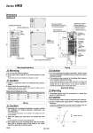
Circulating fluid fill port lid Operation display panel 377 976 Water level indicator Dustproof filter 592 Handle (Same for the opposite side) Caster (unfixed) with locking lever Caster (unfixed) 340 329 323 135 101 939 707 281 143 119 Power cable entry (Grommet with membrane) Maintenance connector Contact input/output communication connector Optional connector 1 Optional connector 2 Circulating fluid return port Rc1/2 Product label Circulating fluid outlet Rc1/2 Facility water outlet Rc1/2 Drain port Rc1/4 (Valve stopper) Facility water inlet Rc1/2 Breaker Serial communication (RS-485/RS-232C) connector D-sub female receptacle Dimensions Mounting/Installation 1. Install on a rigid floor which can withstand this product’s weight. 2. Secure with bolts, anchor bolts, etc. Fasteners such as bolts or anchor bolts should be tighten with the recommended torque shown below. Warning Caution Warning Caution Caution Caution 1. Do not use the product outdoors. 2. Do not place heavy objects on top of this product, or step on it. The external panel can be deformed and danger can result. M3 M4 M5 M6 0.63 1.5 3 5.2 Connection thread Applicable tightening torque (N・m) Fixing Thread Tightening Torque M8 M10 M12 12.5 24.5 42 Connection thread Applicable tightening torque (N・m) Piping 1. Regarding the circulating fluid pipings, consider carefully the suitability for shutoff pressure, temperature and circulating fluid. If the operating performance is not sufficient, the pipings may burst during operation. 2. Select the piping port size which can exceed the rated flow. For the rated flow, refer to the pump capacity table. 3. When tightening at the circulating fluid inlets and outlets, drain port or overflow outlet of this product, use a pipe wrench to clamp the connection ports. Piping 4. For the circulating fluid piping connection, install a drain pan and wastewater collection pit just in case the circulating fluid may leak. 5. This product series consists of circulating fluid temperature controllers with built-in tanks. Do not install equipment on your system side such as pumps that forcibly return the circulating fluid to the unit. Also, if you attach an external tank that is open to the air, it may become impossible to circulate the circulating fluid. Proceed with caution. Electrical Wiring 1. Grounding should never be connected to a water line, gas line or lightning rod. 1. Communication cables should be prepared by the customer. 2. Ensure a stable power supply with no voltage surges and distortion. In particular, operating failure can result when the voltage ramp rate (dV/dt) exceeds 40 V/200 μ sec at the zero cross-over point. dV dV dt dt = Voltage ramp rate Time Voltage HRS050-W Series HRS 1296