6-p0213-0221-kb_en 5 / 10
10秒後にBOOKのページに移動します
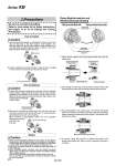
Male module inserted fully into position. Male side (Protruding portion) Female side (Guide portion) Female side (Groove portion) Lock ring Module body (Male side) Module body (Female side) Female side (Window portion) Lock ring (Lock portion) These parts match together These parts match together Match arrows together and insert Do not touch lock ring. Match arrows. Turning lock ring 90° unlocks modules. Do not touch lock ring. How to Install How to Remove Others Piping module-Male side Piping Be sure to read before handling. module-Female side Refer to front matter 56 for Safety Instructions and pages 13 to 16 for Fittings and Tubing Precautions. Series KB Precautions Caution Caution Caution 1. Exhaust the pressure in pipe before removing. If lock is released under pressure, piping material will eject. Turn the lock ring 90° clockwise (in the direction of the arrow). This will cancel out the affects of the lock ring. You need not hold lock ring in place. Lock ring will hold automatically in this position. 2. Remove the modules by pulling apart. Do not touch the lock ring. After removal, the lock ring will return to normal position automatically beause of a return spring. When removed, it automatically rotates 90° in the opposite direction as its spring is built into the lock ring. 1. When connecting piping material to each other, do not apply a bending force, etc. Piping material may be deformed or damaged. If unit is longer than 5 stations, please use brackets or it may result in deformation of the piping material by bends, deflection, etc. 2. Each type of module materials is capable of being piped with all other materials. 3. When attaching female connector union and female connector elbow union, use the body's hexagon surface and tighten threads with a suitable wrench. Use the root nearest the thread when tightening with a wrench. Hex. across flats may be deformed, if using an improper wrench for hex. across flats. 1. Insert each piping module by matching the arrows on the lock ring and the body of the other module. lnsert together. If it becomes difficult to match both modules, rotate modules to left and right while pushing together. When a match is not done, piping material will eject under pressure. 2. Confirm insertion by turning modules to right and left or pulling on them. But do not touch the lock ring in the process. Piping Module-Insertion and Removal Structual Drawing 1. Match arrows together and insert piping module male side into female side. 2. By inserting the lock ring, the lock portion touches female side guide portion and falls into the direction shown with the arrow. 3. By pushing tighter, lock portion goes over female side guide portion and snaps into window slot portion. Male side protruding portion snaps into female side groove portion. This performs the function of a detent. 4. To remove, rotate lock ring 90° to release lock portion from female side window slot, then the lock is released. Removal is complete. 216