5-p0114-0117-id_en 3 / 5
10秒後にBOOKのページに移動します
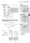
SOL.1 SOL.2 Mist separator Air supply T1. T2. Adsorption tube Adsorption tube Fixed filter Fixed filter Silencer Indicator Check valve DRY AIR Working Principle Flow Rate Inlet pressure: 0.7 MPa Dew Point Condition: Air flow/Rating Recycled Flow Rate Operating System Diagram/Time Chart/Electric Circuit Diagram Operating system diagram Time chart The compressed air that flowed in from the IN side passes through the 4 port solenoid valve, and after it is dehumidified at adsorption cylinder T1, it turns into dry air and exits from the OUT side. Meanwhile, a portion of the dry air passes through orifice O2, it reactivates the adsorption agent at adsorption cylinder T2, and together with moisture, it passes through the solenoid valve and is released to the atmosphere. Conversely, due to the operation of the switching valve that occurs after a certain length of time, T1 becomes reactivated and T2 assumes the adsorption state. This process is repeated to continuously provide dry air. Dry air 1 cycle 1 cycle Series ID尰尰尰-尰尰 Adsorbent/Silica alumina gel Series ID尰尰尰-尰尰Z Adsorbent/Permutite Pressure drop (MPa) Air flow rate (L/min (ANR)) Inlet pressure (MPa) Recycled flow rate (L/min (ANR)) Outlet air dew point temp. (°C) (Atm.temp.) Inlet air pressure 0.3 MPa Inlet air temperature (°C) (Saturation) 0.5 MPa 0.7 MPa Heatless Air Dryer Series ID SOL.1 SOL.2 F SW 4 port solenoid valve 4 port solenoid valve Fuse Snap switch Symbol PL LS1,2 MR Light Micro switch Timing motor Resistor Description Symbol Description For ID尰00, ID尰01 For ID尰05, ID尰06 Power supply (refer to “How to Order”) Power supply (refer to “How to Order”) F SOL.1 LS2 SOL.2 LS1 M PL SV SV F SW SOL.1 LS2 SOL.2 LS1 M PL SV SV SW R Electric circuit 115 HAA HAW AT IDF IDU IDFA IDFB IDH ID IDG IDK AMG AFF AM AMD AMH AME AMF ZFC SF SFD LLB AD𡱖 GD