4-p0147-0178-msu-mdsu_en 6 / 33
10秒後にBOOKのページに移動します
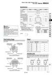
When operating an actuator with a small diameter and a short stroke at a high frequency, the dew condensation (water droplet) may occur inside the piping depending on the conditions. Simply connecting the moisture control tube to the actuator will prevent dew condensation from occurring. For details, refer to Series IDK in the WEB catalog. Moisture Control Tube Series IDK Note) Values above do not include auto switch weight. MSUA1 MSUA3 MSUA7 MSUA20 Air (Non-lube) 5 to 60°C Special bearing Side ported or Top ported 0.03 mm or less 0.2 to 0.7 0.15 to 0.7 M3 x 0.5 M3 x 0.5 M5 x 0.8 20 N 15 N 0.3 N・m 40 N 30 N 0.7 N・m 50 N 60 N 0.9 N・m M5 x 0.8 60 N 80 N 2.9 N・m 0.07 to 0.3 (0.5 MPa) 1.05 1.5 0.15 to 1.0 Rotary table MSUA 1 MSUA 3 MSUA 7 MSUA20 Free-mount rotary actuator CRBU2W10 CRBU2W15 CRBU2W20 CRBU2W30 Size 1 3 7 20 Auto switch unit Note) 15 20 28 38 90° 180° 90° 180° 90° 180° 90° 180° 162 161 262 260 440 436 675 671 Size 1 3 7 20 Allowable radial load (N) 20 40 50 60 Allowable moment (N・m) 0.3 0.7 0.9 2.9 Allowable thrust load (N) 15 30 60 80 Symbol Series MSUA Rotary Table: High Precision Type Vane Style Specifications Model .2 Vane type Rotating angle .1 Fluid Proof pressure (MPa) Ambient and fluid temperature Operating pressure range (MPa) Rotation time adjustment range (s/90°) Shaft load Bearing Port location Port size Deflection accuracy Allowable radial load Allowable thrust load Allowable moment Side ported Top ported 90° ± 10° 180° ± 10° 90° ± 10° 180° ± 10° 90° ± 10° 180° ± 10° 90° ± 10° 180° ± 10° Single vane . 2 Correspondence to equivalent conventional free-mount types Angle adjustment is possible as shown in the drawings below using adjustment bolts (A) and (B). Table Rotation Range Weight Single vane (S): 80 to 100° adjustable For 90° rotation Single vane (S): 170 to 190° adjustable For 180° rotation Adjustment range of adjustment bolt (A) Adjustment range of adjustment bolt (B) Adjustment range of adjustment bolt (B) 90° 22.5° 22.5° Positioning pin hole Adjustment bolt (A) Adjustment bolt (B) 10° (± 5°) 10° (± 5°) Positioning pin hole Adjustment bolt (A) Adjustment bolt (B) 180° Adjustment range of adjustment bolt (A) Rotating angle Basic weight (g) Single vane Allowable Load Do not permit the load and moment applied to the table to exceed the allowable values shown in the table below. (Operation above the allowable values can cause adverse effects on service life, such as play in the table and loss of accuracy.) (S): 10° (± 5°) (S): 10° (± 5°) . 1 Single vane 90° can be adjusted to 90° ± 10° (both ends of rotation ± 5° each) Single vane 180° can be adjusted to 180° ± 10° (both ends of rotation ± 5° each) Note) Refer to page 35 for allowable kinetic energy. 151 CRB2 -Z CRBU2 CRB1 MSU CRJ CRA1 -Z CRA1 CRQ2 MSQ MSZ CRQ2X MSQX MRQ D- A