4-p0147-0178-msu-mdsu_en 31 / 33
10秒後にBOOKのページに移動します
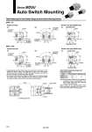
Model MDSU1, 3 MDSU7, 20 Auto Switch Operating Angle and Hysteresis Angle Single vane type Double vane type (MSUB only) MSU7/20 Single vane type Double vane type (MSUB only) Auto Switch for END 1 Auto Switch for END 1 Auto Switch for END 1 Auto Switch for END 1 Auto Switch for END 1 Auto Switch for END 1 Auto Switch for END 2 Auto Switch for END 2 Auto Switch for END 2 Auto Switch for END 2 Auto Switch for END 2 Auto Switch for END 2 Series MDSU Auto Switch Mounting Table Positioning Pin Hole Rotation Range and Auto Switch Mounting Position MSU1/3 . In drawings that show the rotation range, the arrows on the solid line 90° (180°) indicate the rotation range of the positioning pin holes on the table surface. When the pin hole is at END1, the END1 auto switch operates, and when the pin hole is at END2, the END2 auto switch operates. . The arrows on the broken line indicate the rotation range of the internal magnet. The rotation range of each auto switch can be reduced by moving the END1 auto switch clockwise and the END2 auto switch counterclockwise. 110° 90° Hysteresis angle 10° Operating angle Note) Since the above values are only provided as a guideline, they are not guaranteed. In the actual setting, adjust them after confirming the auto switch performance. Refer to page 142 for operating angle of auto switch and angle of hysteresis and the procedure for moving the auto switch detection position. Table Positioning pin hole B port A port Auto switch 176