4-p0113-0145-crb1-cdrb1_en 29 / 34
10秒後にBOOKのページに移動します
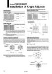
Note 1) For size 40, each stopper block comes with 2 holding bolts. Note 2) Since the angle adjustment block has been secured temporarily at shipment, please adjust and secure this block firmly before using the rotary actuator. Model CRB2BWU10, CRBU2WU10 CRB2BWU15, CRBU2WU15 CRB2BWU20, CRBU2WU20 CRB2BWU30, CRBU2WU30 CRB2BWU40, CRBU2WU40 Rotation adjustment range 0 to 230° 0 to 240° 0 to 230° Rubber bumper Yes Model CRB2BWU10, CRBU2WU10 CRB2BWU15, CRBU2WU15 CRB2BWU20, CRBU2WU20 CRB2BWU30, CRBU2WU30 CRB2BWU40, CRBU2WU40 Tightening torque (N・m) 1.0 to 1.2 2.5 to 2.9 3.4 to 3.9 Model CRB2BWU10, CRBU2WU10 CRB2BWU15, CRBU2WU15 CRB2BWU20, CRBU2WU20 CRB2BWU30, CRBU2WU30 CRB2BWU40, CRBU2WU40 Rotation adjustment range 0 to 90° Rubber bumper Yes Series CRB2/CRBU2 Installation of Angle Adjuster Specifications Single Vane Type Recommended Tightening Torque for Holding Stopper Block Double Vane Type Note) Stopper block is tightened temporarily at the time of shipment. Angle is not adjusted before shipment. Note 1) Use rotary actuator for 270°. Note 2) Connection ports are side ports only. Note 3) The allowable kinetic energy is the same as the specifications of the rotary actuator by itself. Note 1) Since the maximum angle of the rotation adjustment range will be limited by the rotation when using a rotary actuator for 90°, make sure to take this into consideration when ordering. Rotary actuator for 90° should be used to adjust the angle of 85° or less as a guide. Note 2) Connection ports are side ports only. Note 3) The allowable kinetic energy is the same as the specifications of the rotary actuator by itself. Rotation Adjustment Method Remove the resin cap in the illustrations below, slide the stopper block on the long groove and lock it into the appropriate position to adjust the rotation and rotation position. Protruding four chamfers for wrench on the output shaft that rotates allows manual operation and convenient positioning. (Refer to the rotation setting examples shown in the next page for details.) Other Operating Method Although one stopper block is mounted on each long groove for standard specifications as shown in the illustrations below, 2 stopper blocks can be mounted on one long groove. Angle adjustment range when 2 stopper blocks are mounted on a single long groove Size: 10, 40 ・・・・・・・・・・・・・・・・・・50° Size: 15, 20, 30 ・・・・・・・・・・・・60° As shown in