4-p0113-0145-crb1-cdrb1_en 18 / 34
10秒後にBOOKのページに移動します
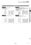
Double Shaft Size 50 63 80 100 d1 (mm) M5 x 0.8 M6 x 1 M8 x 1.25 50 o4.2 . . (mm) 63 o4.2 o5 . 80 o4.2 o5 . 100 . o5 o6.8 d1 = o Q1 = M Q1 L1 L1 = o4 to o5 o4 to o6 o4 to o6.5 o5 to o8 Symbol: A19 Symbol: A20 Size 50 63 80 100 Y 24.5 to 39.5 28 to 45 30.5 to 53.5 40 to 65 X 4 to 19.5 4 to 21 4 to 23.5 5 to 30 (mm) Size 50 63 80 100 Y 24.5 to 39.5 28 to 45 30.5 to 53.5 40 to 65 X 4 to 19.5 4 to 21 4 to 23.5 5 to 30 (mm) Y = X = Y = X = Symbol: A13 Applicable to single vane type only Shaft with through-hole . Minimum machining diametor for d1 is 0.1. . Applicable shaft type: W Shorten both long and short shafts. . Applicable shaft type: W Symbol: A16 Applicable to single vane type only Size Thread A special end is machined onto both the long and short shafts, and a through hole is drilled into both shafts. Female threads are machined into the through-holes, whose diameter is equivalent to the diameter of the pilot holes. . The maximum dimension L1 is, as a rule, twice the thread size. (Example) For M5: L1 = 10 . Applicable shaft type: W . Equal dimensions are indicated by the same marker. The rotation axis is reversed. (If shortening the shaft is not required, indicate “.” for dimension X, Y.) . Applicable shaft type: W Simple Specials Series CRB1 129 CRB2 -Z CRBU2 CRB1 MSU CRJ CRA1 -Z CRA1 CRQ2 MSQ MSZ CRQ2X MSQX MRQ D-