4-p0113-0145-crb1-cdrb1_en 15 / 34
10秒後にBOOKのページに移動します
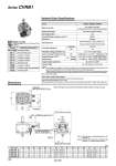
Model (Size) CVRB1BW 50 CVRB1BW 63 CVRB1BW 80 CVRB1BW100 A1 78 98 110 140 A2 67 82 95 125 B1 18 18 22 22 B2 36 36 48 48 B3 2.8 2.8 4 4 D1 12 16 17 23.5 D2 24 24 29 29 E1 11.5 11.5 14 14 E2 30 30 38 38 G 25 27.5 36 42.5 R 1/8 1/8 1/8 1/8 C1 82.5 88 100 100 C2 120 (136.5) 102 (136.5) 140 (155 ) 140 (155 ) C3 60 (61) 60 (61) 70 (71) 70 (71) F1 52 (53) 52 (53) 62 (63) 62 (63) F2 104 (120.5) 104 (120.5) 124 (139 ) 124 (139 ) (mm) Dimensions Model Manual override Pilot exhaust type Mounting position Impact/Vibration resistance (m/s2) (1) Enclosure Electrical entry Coil rated voltage (V) Allowable voltage fluctuation (%) Power consumption (2) (W) [Current mA] Apparent power (VA) (2) [Current mA] Surge voltage suppressor Indicator light AC50/60Hz DC DC AC Inrush Holding Series VZ3000, VZ5000 Pilot valve individual exhaust Free 300/50 Dusttight Grommet (G)/(H), L plug connector (L), M plug connector (M), DIN terminal (D) 100, 200 24 .15 to +10 of rated voltage 1.8 (With light: 2.1) (24 VDC: 75 [With light: 87.5]) 4.5 to 50Hz, 4.2/60Hz 3.5 /50Hz, 3 /60Hz DC: Diode, AC: ZNR DC: LED (Red), AC: Neon bulb 100 VAC: 45/50Hz, 42/60Hz 200 VAC: 22.5/50Hz, 21/60Hz 100 VAC: 35/50Hz, 30/60Hz 200 VAC: 17.5/50Hz, 15/60Hz Non-locking push type Locking type (Slotted), Locking type (Manual) . Keys in the figures above show the intermediate rotation position for single vane type. Made to Order (Refer to pages 127 to 129, 136 and 137 for details.) Symbol Specifications/Description Shaft type pattern Add connection port Change of rotation Change of rotation Change of rotation Reversed shaft Change of rotation Change of rotation range and direction Fluorine grease XA1 to XA24 XC 1 XC 4 XC 5 XC 6 XC 7 XC26 XC27 XC30 Solenoid Valve Specifications (When double solenoid is mounted) Solenoid B Solenoid A .B2 B3 (When the needle is fully open) 2 x metering valve with silencer (EXH) ASN2-M5 (CVRB1BW50) ASN2-01 (CVRB1BW80, 100) C2 (When double solenoid is mounted) F2 (When double solenoid is mounted) About rotary actuator specifications The vibration adjustment range differs from that of the standard series. Solenoid valve specifications: 0.3 to 1s/90° Other specifications and structures are similar to those of the standard series CRB1. Please refer to page 120. 35 Note 1) Solenoid valve in external appearance is for VZ 140-1G. Note 2) Solenoid valve dimensions: 2 position single solenoid, ( ): 2 position double solenoid. Series CVRB1 . Option Note 1) Impact resistance: No malfunction occurred in the impact test using a drop impact tester. The test was performed at both energized and de-energized states to the axis and right angle direction of the main valve and armature. Vibration resistance: No malfunction occurred in the one-sweep test between 45 and 2000 Hz. A test was performed at both energized and de-energized states to the axis and right angle direction of the main valve and armature. (Value in the initial stage.) Note 2) At the rated voltage. 126