p-10-2a-isocyБ@Б@Б@67 / 71
10ХbМгВ…BOOKВћГyБ[ГW…ȏӁµ¹£
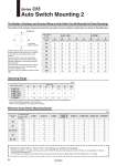
. The operating ranges are provided as guidelines including hystereses and are not guaranteed values (assuming approximately Б}30% variations). They may vary significantly with ambient environments. A C D B View from piston rod end The number of the surfaces and grooves where the auto switch can be mounted, by switch type, are shown in the table below. 20 25 32, 40, 50 63 80, 100 2 pcs. 1 pc. 2 pcs. 1 pc. 2 pcs. 1 pc. 2 pcs. 1 pc. 2 pcs. 1 pc. D-A9рЃ 10 10 10 10 10 10 10 5 10 10 D-A9рЃV 10 5 10 5 10 5 10 5 10 5 D-M9рЃ 15 15 10 10 10 10 10 5 15 15 D-M9рЃW D-M9рЃA 15 15 15 15 15 15 15 15 15 15 D-M9рЃV 5 5 5 5 5 5 5 5 5 5 D-M9рЃWV 10 5 10 5 10 5 10 5 10 5 D-M9рЃAV 10 10 10 10 10 10 10 10 10 10 D-P3DWрЃ 15 15 15 15 10 10 10 10 10 10 (mm) D-A9рЃ(V) D-P3DWрЃ D-M9рЃ(V) D-M9рЃW(V) D-M9рЃA(V) Auto switch model Bore size (mm) 9 5 5 9 4.5 5.5 9 5 5.5 9 4 5.5 9 4.5 5.5 10.5 5 6.5 14 10 9 20 25 32 40 50 63 80 100 10.5 8 7 Auto switch model D-A9рЃ, M9рЃ D-P3DWрЃ A B C D A B C D 20 25 32 40 50 63 80 100 Bore size (mm) рЈ (2) рЈ (2) рЈ (2) рЈ (2) рЈ (2) рЈ (2) рЈ (2) рЈ (2) рЈ (2) рЈ (2) рЈ (2) рЈ (2) рЈ (2) рЈ (2) рЈ (2) рЈ (2) рЈ (2) рЈ (2) рЈ (2) рЈ (2) рЈ (1) рЈ (2) рЈ (2) рЈ (2) рЈ (2) рЈ (2) рЈ (2) рЈ (2) рЈ (2) рЈ (2) рЈ (2) рЈ (2) рЈ (2) рЈ (2) рЈ (2) рЈ (2) рЈ (2) рЈ (2) рЈ (2) рЈ (2) рЈ (2) рЈ (2) рЈ (2) рЈ (2) рЈ (2) рЈ (2) рЈ (2) рЈ (2) рЈ (2) рЈ (2) рґ рґ рґ рґ рґ рґ рЈ (2) рЈ (2) рЈ (2) рЈ (2) рЈ (2) рЈ (2) рЈ (2) рЈ (2) Series C55 Auto Switch Mounting 2 The Number of Surfaces and Grooves Where an Auto Switch Can Be Mounted (As Direct Mounting) Piping port Mounting the D-P3DWрЃ on a o20 to o25 port surface interferes with the fitting, so it needs to be mounted on a place other than the port surface. For o32 to o100, if the corner of the fitting hexagon interferes with the D-P3DWрЃ series, adjust the tightening of the fitting to eliminate the interference. Also, in the case of interference with an elbow type fitting, direct the port of the fitting away from the D-P3DWрЃ series. If you have any other questions, please contact SMC. (Mounting groove no.) (Mounting groove no.) (Mounting groove no.) (Mounting groove no.) (Mounting groove no.) (Mounting groove no.) (Mounting groove no.) (Mounting groove no.) Operating Range Minimum Auto Switch Mounting Stroke Auto switch model No. of auto switch mounted Bore size (mm) Besides the models listed in БgHow to Order,Бh the following auto switches are applicable. . Normally closed (NC = b contact) solid state auto switch (D-F9G/F9H type) and solid state auto switch D-F8 type are also available. For details, refer to Best Pneumatics No. 2. . For solid state auto switches, auto switches with a pre-wired connector are also available. Refer to Best Pneumatics No. 2 for details. 64