p-10-2a-isocy 66 / 71
10秒後にBOOKのページに移動します
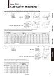
. Hs . Hs W W A B A A B A B B . Hs . Hs o20, o25 o32, o40, o50, o63, o80, o100 Auto switch model Bore size (mm) 20 25 32 40 50 63 80 100 B W A B W A B W D-M9A A B W Hs D-P3DW (mm) D-A9 D-M9 D-M9W The dimension inside ( ) is for D-A96. Negative figures in the table W indicate an auto switch is mounted inward from the edge of the cylinder body. o32, o40, o50, o63, o80, o100 o20, o25 A 20 25 32 40 50 63 80 100 5.5 7.5 9.5 12 15.5 18.5 17.5 22.5 22 24 27 30 36 41 49.5 60 15.5 16.5 18.5 17 13.5 14.5 20.5 28.5 9.5 11.5 13.5 16 19.5 22.5 21.5 26.5 A B Hs A B Hs 24 26 29 32 38 43 52 62 D-A9V D-M9V D-M9WV D-M9AV 11.5 12.5 14.5 13 9.5 10.5 16.5 24.5 . Figures in the table below are used as a reference when mounting the auto switches for stroke end detection. In the case of actually setting the auto switches, adjust them after confirming their operation. Auto switch model Bore size (mm) 5.5 7.5 9.5 12 15.5 18.5 17.5 22.5 1 (3.5) 3 (5.5) 5 (7.5) 7.5 (10) 11 (13.5) 14 (16.5) 13 (15.5) 18 (20.5) 15.5 16.5 18.5 17 13.5 14.5 20.5 28.5 9.5 11.5 13.5 16 19.5 22.5 21.5 26.5 .2.5 .0.5 1.5 4 7.5 10.5 9.5 14.5 15.5 16.5 18.5 17 13.5 14.5 20.5 28.5 9.5 11.5 13.5 16 19.5 22.5 21.5 26.5 .0.5 1.5 3.5 6 9.5 12.5 11.5 16.5 6.0 7 9.5 8 4.5 5.5 11.5 19.5 0.5 2.5 4 7 10.5 13.5 12.5 17.5 .3.0 .1 1 3.5 7 10 9 14 30 32 35 38 44 49 57.5 67.5 11.5 12.5 14.5 13 9.5 10.5 16.5 24.5 Proper Auto Switch Mounting Position (Detection at Stroke End) and Its Mounting Height Series C55 Auto Switch Mounting 1 Reed auto switch D-M9 D-M9W D-M9A D-P3DW Solid state auto switch D-A9 Reed auto switch Solid state auto switch D-A9V D-M9V D-M9WV D-M9AV (mm) . Figures in the table below are used as a reference when mounting the auto switches for stroke end detection. In the case of actually setting the auto switches, adjust them after confirming their operation. Series C55 Series C96 Series CP96 Series C85 63