p-10-2a-isocy 61 / 71
10秒後にBOOKのページに移動します
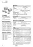
Type Action Fluid Proof pressure Maximum operating pressure Minimum operating pressure Pneumatic (Non-lube) Double acting, Single rod Air 1.5 MPa 1.0 MPa 0.05 MPa (o20 to o63), 0.03 MPa (o80, o100) Without auto switch: .10 to 70°C (No freezing) With auto switch: .10 to 60°C (No freezing) Rubber bumper on both end 50 to 500 mm/s 50 to 300 mm/s Ambient and fluid temperature Piston speed o20 to o63 o80, o100 Cushion Stroke length tolerance Note) Add each weight of auto switches and mounting brackets when mounting an auto switches. Refer to Best Pneumatics No. 2 for auto switch weight. Unit: g Bore size (mm) 5 113 154 254 319 502 685 . . 20 25 32 40 50 63 80 100 10 126 170 277 344 539 725 1188 2248 15 139 185 299 368 575 765 1246 2330 20 152 201 321 392 612 805 1305 2412 25 165 217 343 416 649 845 1363 2494 30 178 232 366 441 686 885 1421 2577 35 191 248 388 465 723 925 1480 2659 40 204 263 410 489 760 965 1538 2741 45 216 279 432 513 796 1005 1596 2823 50 229 294 455 537 833 1045 1654 2905 60 255 325 499 586 907 1125 1771 3069 80 307 388 588 683 1054 1285 2004 3397 100 359 450 677 780 1202 1445 2238 3726 125 424 528 788 901 1386 1645 2529 4136 150 489 606 900 1022 1570 1845 . . With Auto Switch (Built-in magnet) Cylinder stroke (mm) Bore size (mm) Cylinder stroke (mm) 5 111 152 250 315 497 677 . . 20 25 32 40 50 63 80 100 10 124 168 273 339 534 717 1164 2213 15 137 183 295 364 570 757 1223 2295 20 150 199 317 388 607 797 1281 2377 25 163 214 339 412 644 837 1339 2459 30 176 230 362 436 681 877 1398 2541 35 189 246 384 461 718 917 1456 2623 40 202 261 406 485 755 957 1514 2705 45 215 277 428 509 791 997 1573 2787 50 228 292 451 533 828 1037 1631 2870 60 254 323 495 582 902 1117 1748 3034 80 306 386 584 679 1049 1277 1981 3362 100 357 448 673 776 1197 1437 2214 3690 125 422 526 785 897 1381 1638 2506 4101 150 487 603 896 1018 1565 1838 . . 20 25 32 40 50 63 80 100 C55-L020 C55-L025 C55-L032 C55-L040 C55-L050 C55-L063 C55-L080 C55-L100 C55-F020 C55-F025 C55-F032 C55-F040 C55-F050 C55-F063 C55-F080 C55-F100 C55-C020 C55-C025 C55-C032 C55-C040 C55-C050 C55-C063 C55-C080 C55-C100 . Order two foot brackets per cylinder. . Parts belonging to each bracket are as follows. Foot, Flange, Single clevis/Body mounting bolt Note) Stroke length tolerance does not include the amount of bumper change. Bore size (mm) Kit no. Contents CQ2B20-PS CQ2B25-PS CQ2B32-PS CQ2B40-PS CQ2B50-PS CQ2B63-PS CQ2B80-PS Rod seal Piston seal Tube gasket 20 25 32 40 50 63 80 100 CQ2B100-PS Specifications +1.0 0 mm Weight Without Auto Swtich Unit: g Manufacture of Intermediate Stroke Standard Stroke Bore size (mm) Standard stroke (mm) 5, 10, 15, 20, 25, 30, 35, 40, 45, 50, 60, 80, 100, 125, 150 10, 15, 20, 25, 30, 35, 40, 45, 50, 60, 80, 100, 125 20 to 63 80, 100 Dealing with the stroke by the 1 mm interval by using an exclusive body with the specified stroke Refer to “How to Order” for the standard model no. (page 57) 6 to 149 Part no.: C55B32-47 Makes 47 stroke tube Description Part no. Stroke range Example Caution Be sure to read before handling. qRefer to back cover for Safety Instructions and “Handling Precautions for SMC Product” (M-E03-3) for Actuators and Auto Switches Precautions. wThis product should not be used as a stopper. eUse the PF thread fittings for this cylinder. Bore size (mm) Foot Flange Single clevis Mounting Bracket Part No. Replacement Parts/Seal Kit 58 Series C55