p-10-2a-isocy 42 / 71
10秒後にBOOKのページに移動します
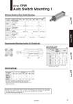
A B Auto switch model Number of auto switch mounted 32 40 50 63 80 100 125 2 switches (Different side, Same side) D-M9尰 D-A9尰 D-M9尰W D-M9尰A Note) n = 3, 4, 5 ・・・ Bore size Auto switch model D-M9尰 D-M9尰W D-M9尰A D-A9尰 A B A B 10.5 10.5 11 11 14 14 16 6.5 6.5 7 7 10 10 12 8 8 8.5 8.5 12.5 12.5 16 4 4 4.5 4.5 8.5 8.5 12 32 40 50 63 80 100 125 (mm) (mm) Auto switch model Bore size 32 40 50 63 80 100 125 4 4 5 6 5.5 6 7 7 8 8.5 9.5 9.5 10.5 12.5 D-M9尰 D-M9尰W D-M9尰A D-A9尰 (mm) 1 switch Other qty. 1 switch Other qty. 2 switches (Different side, Same side) 1 switch Other qty. Auto Switch Proper Mounting Position Note) Adjust the auto switch after confirming the operation to set actually. . Since this is a guideline including hysteresis, not meant to be guaranteed. (Assuming approximately ±30% dispersion) There may be the case it will vary substantially depending on an ambient environment. 2 switches (Different side, Same side) Minimum Stroke for Auto Switch Mounting Recommended Mounting Position for Stroke Ends 15 10 15 15+5 (n-2) 10 10+10 (n-2) 15 10 15 15+10 (n-2) 10 10+10 (n-2) 10+15 (n-2) 15 15 15+10 (n-2) 15+15 (n-2) 15+20 (n-2) 10 Besides the models listed “How to Order,” the following auto switches are applicable. . Normally closed (NC = b contact) solid state switch (D-F9G, F9H type) are also available. For details, refer to Best Pneumatics No. 2. Series CP96 Auto Switch Mounting 1 Operating Range Series C55 Series C96 Series CP96 Series C85 39