2-p0777-0973-cq2-z_en 53 / 248
10秒後にBOOKのページに移動します
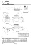
oD oD Q Q L S U EB EA E M K H1 C1 X H1 C1 X L1 R R K M E S U 8 O1 thread A + 2 (Stroke) B + Stroke L + Stroke V Auto switch Width across flat K Minimum lead wire bending radius 10 2 x M5 x 0.8 (Port size) H thread effective depth C 2 x oN through 4 x oO counterbore A1 + 2 (Stroke) L1 + Stroke 2 x MM Width across flat B1 Width across flat B1 2 x oN through 4 x oO counterbore H thread effective depth C V 12 16 20 25 O1 M4 x 0.7 M4 x 0.7 M6 x 1.0 M6 x 1.0 R 7 7 10 10 12 16 20 25 5 to 30 5 to 30 5 to 50 5 to 50 A 39.4 43 47 49 B 32.4 36 38 39 C 6 8 7 12 D 6 8 10 12 E 33 37 47 52 EA . 13.2 13.6 13.6 EB . 6.6 6.8 6.8 K 5 6 8 10 L 3.5 3.5 4.5 5 M 22 28 36 40 N 3.5 3.5 5.5 5.5 Q 10.5 10 8 9 S 27.5 29.5 35.5 40.5 U 14 15 18 21 V 25 29 36 40 H M3 x 0.5 M4 x 0.7 M5 x 0.8 M6 x 1.0 (mm) 12 16 20 25 A1 60.4 67 75 84 C1 9 10 12 15 H1 4 5 5 6 L1 14 15.5 18.5 22.5 B1 8 10 13 17 MM M5 x 0.8 M6 x 1.0 M8 x 1.25 M10 x 1.25 X 10.5 12 14 17.5 o12 o16 to o25 o12 to o25/With Auto Switch Dimensions Standard (Through-hole): CDQ2WB Both ends tapped: CDQ2WA Bore size (mm) Note 1) The positions of left and right width across flats are not constant. Both Ends Tapped (mm) Rod end male thread Rod End Male Thread Bore size (mm) Note 2) The external dimensions with rubber bumper are same as those of the standard, as shown above. . For details about the rod end nut and accessory brackets, refer to page 804. Standard For auto switch proper mounting position and its mounting height, refer to pages 954 to 960. Bore size (mm) Stroke range (mm) O 6.5 depth 3.5 6.5 depth 3.5 9 depth 7 9 depth 7 (mm) Series CQ2W 816