2-p0777-0973-cq2-z_enҒ@Ғ@Ғ@44 / 248
10•bҢгӮЙBOOKӮМғyҒ[ғWӮЙҲЪ“®ӮөӮЬӮ·
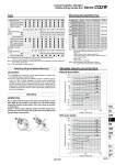
o100 o80 o63 o50 o40 o32 o25 o20 o16 o12 o100 o80 o63 o50 o40 o32 o25 o20 o16 o12 300 200 100 50 40 30 20 10 5.0 4.0 3.0 2.0 1.0 0 50 100 300 200 100 50 40 30 20 10 5.0 4.0 3.0 2.0 1.0 0 50 100 Allowable lateral load at rod end (N) Allowable lateral load at rod end (N) Cylinder stroke (mm) Cylinder stroke (mm) Retaining Ring Installation/Removal Caution Mounting Warning 1. For installation and removal, use an appropriate pair of pliers (tool for installing a type C retaining ring). 2. Even if a proper plier (tool for installing a type C retaining ring) is used, it is likely to inflict damage to a human body or peripheral equipment, as a retaining ring may be flown out of the tip of a plier (tool for installing a type C retaining ring). Be much careful with the popping of a retaining ring. Besides, be certain that a retaining ring is placed firmly into the groove of rod cover before supplying air at the time of installment. Do not apply reverse torque to the piston rods sticking out from both sides of this cylinder at the same time. The torque makes connection threads inside loosen, which may cause an accident or malfunction. Install or remove loads while the piston rod width across flat is secured. Do not fix the other side of the piston rod width across flat and apply reverse torque. Note 1) o32 without auto switch: M5 x 0.8 is used for 5 mm strokepiping dimension. Thus, do not enter a symbol for the port thread type. Note 2) The dimension of the o32-5 mm stroke with built-in One-touch fittings is the same as that of the 10 mm stroke cylinder tube. Note 3) One-touch fittings cannot be replaced. With Auto Switch 12 16 20 25 32 40 50 63 80 100 CQ-L012 CQ-LZ12 CQ-L016 CQ-LZ16 CQ-L020 CQ-LZ20 CQ-L025 CQ-LZ25 CQ-L032 CQ-L040 CQ-L050 CQ-L063 CQ-L080 CQ-L100 CQ2рӯрӯ-рӯD CQ2рӯрӯ-рӯDZ CQ2рӯрӯ-рӯD CQ2рӯрӯ-рӯDZ CQ2рӯрӯ-рӯD CQ2рӯрӯ-рӯDZ CQ2рӯрӯ-рӯD CQ2рӯрӯ-рӯDZ CQ2рӯрӯ-рӯDZ CQ2рӯрӯ-рӯDZ CQ2рӯрӯ-рӯDZ CQ2рӯрӯ-рӯDZ CQ2рӯрӯ-рӯDZ CQ2рӯрӯ-рӯDZ CQ-F012 CQ-F016 CQ-F020 CQ-F025 CQ-F032 CQ-F040 CQ-F050 CQ-F063 CQ-F080 CQ-F100 Type Mounting Brackets/Part No. Bore size (mm) Foot Note 4) CQ-LC012 CQ-LCZ12 CQ-LC016 CQ-LCZ16 CQ-LC020 CQ-LCZ20 CQ-LC025 CQ-LCZ25 CQ-LC032 CQ-LC040 CQ-LC050 CQ-LC063 CQ-LC080 CQ-LC100 Model Compact foot Note 4) Flange Without switch With switch Without switch With switch Without switch With switch Without switch With switch Note 4) When ordering foot and compact foot brackets, the required quantity will be different depending on the bore size. o12 to o25: . Without switch: Order 2 pieces per cylinder. . With switch: Order 1 piece per cylinder. (Part number for a set of 2 foot brackets) o32 to o100: . Order 2 pieces per cylinder. Note 5) Parts belonging to each bracket are as follows. Foot, Compact foot, Flange: Body mounting bolts Allowable Lateral Load at Rod End Without Auto Switch Series CQ2W Compact Cylinder: Standard Double Acting, Double Rod Bore size (mm) Piping Mounting Piping Mounting Through-hole (Standard) Both ends tapped Through-hole (Standard) Both ends tapped Built-in magnet Built-in magnet Rod end male thread With rubber bumper Rod end male thread Pipe thread Pipe thread Built-in One-touch fittings Note 3) 12 р‘р‘р‘ . . . р‘р‘ . . . . . . 16 р‘р‘р‘ . . . р‘р‘ . . . . . . 20 р‘р‘р‘ . . . р‘р‘р‘р‘р‘ . р‘ 25 р‘р‘р‘ . . . р‘р‘р‘р‘р‘ . р‘ 32 р‘р‘р‘ NPT1/8 G1/8 o6 Note 2) р‘р‘р‘р‘р‘ NPT1/8 р‘ 40 р‘р‘р‘ NPT1/8 G1/8 o6 р‘р‘р‘р‘р‘ NPT1/8 р‘ 50 р‘р‘р‘ NPT1/4 G1/4 o8 р‘р‘р‘р‘р‘ NPT1/4 р‘ 63 р‘р‘р‘ NPT1/4 G1/4 o8 р‘р‘р‘р‘р‘ NPT1/4 р‘ 80 р‘р‘р‘ NPT3/8 G3/8 . р‘р‘р‘р‘р‘ NPT3/8 р‘ 100 р‘р‘р‘ NPT3/8 G3/8 . р‘р‘р‘р‘р‘ NPT3/8 р‘ M5 x 0.8 M5 x 0.8 M5 x 0.8 M5 x 0.8 M5 x 0.8 M5 x 0.8 Note 1) M5 x 0.8 Rc1/8 Note 1) M5 x 0.8 Rc1/8 Rc1/8 Rc1/4 Rc1/4 Rc3/8 Rc3/8 Rc1/8 Rc1/4 Rc1/4 Rc3/8 Rc3/8 . TN . TN TF Air-hydro Pneumatic 809 CUJ CU CQS RQ CQM CQU MU -Z D-р® -Xр® Technical data CQ2 -Z A