2-p0777-0973-cq2-z_en 27 / 248
10秒後にBOOKのページに移動します
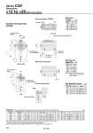
S U EB EA H1 C1 X L1 G oTh9 R R oD Q F L E M K MM K M E S U (mm) 12 16 20 25 5 to 30 5 to 30 5 to 50 5 to 50 A 31.5 34 36 37.5 B 28 30.5 31.5 32.5 C 6 8 7 12 D 6 8 10 12 E 33 37 47 52 EA . 13.2 13.6 13.6 EB . 6.6 6.8 6.8 F 6.5 5.5 5.5 5.5 H M3 x 0.5 M4 x 0.7 M5 x 0.8 M6 x 1.0 K 5 6 8 10 L 3.5 3.5 4.5 5 M 22 28 36 40 N 3.5 3.5 5.5 5.5 O 6.5 depth 3.5 6.5 depth 3.5 9 depth 7 9 depth 7 Q 11 10 8 9 S 27.5 29.5 35.5 40.5 U 14 15 18 21 V 25 29 36 40 V o12 o16 to o25 8 o12 to o25/With Auto Switch Dimensions R 7 7 10 10 Both Ends Tapped Bore size (mm) 12 16 20 25 O1 M4 x 0.7 M4 x 0.7 M6 x 1.0 M6 x 1.0 (mm) With Boss on Head End (mm) Bore size (mm) 12 16 20 25 G 1.5 1.5 2 2 Th9 15 0 .0.043 20 0 .0.052 13 0 .0.043 15 0 .0.043 Note 1) With boss on rod end: Option (Suffix “-XC36” to the end of model number.) Rod End Male Thread Bore size (mm) 12 16 20 25 C1 9 10 12 15 H1 4 5 5 6 B1 8 10 13 17 L1 14 15.5 18.5 22.5 MM M5 x 0.8 M6 x 1.0 M8 x 1.25 M10 x 1.25 X 10.5 12 14 17.5 (mm) Standard (Through-hole): CDQ2B Both ends tapped: CDQ2A O1 thread With boss on head end B + Stroke A + Stroke Auto switch Minimum lead wire bending radius 10 2 x M5 x 0.8 (Port size) H thread effective depth C 2 x oN through 4 x oO counterbore Rod end male thread Width across flat B1 2 x oN through 4 x oO counterbore H thread effective depth C V Note 2) The external dimensions with rubber bumper are same as those of the standard, as shown above. . For details about the rod end nut and accessory brackets, refer to page 804. Note 3) For calculation on the longitudinal dimension of intermediate strokes, refer to page 787. Standard For auto switch proper mounting position and its mounting height, refer to pages 954 to 960. Bore size (mm) Stroke range (mm) Series CQ2 798