2-p0777-0973-cq2-z_en 23 / 248
10秒後にBOOKのページに移動します
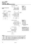
R R G oTh9 oD Q F L oI E M Z K M E H1 C1 X L1 MM H thread effective depth C 8 x oO counterbore 4 x oN through O1 thread B + Stroke A + Stroke (Port size) 2 x M5 x 0.8 Width across flat B1 L1 14 15.5 18.5 22.5 Rod End Male Thread Bore size (mm) 12 16 20 25 C1 9 10 12 15 B1 8 10 13 17 H1 4 5 5 6 X 10.5 12 14 17.5 MM M5 x 0.8 M6 x 1.0 M8 x 1.25 M10 x 1.25 Standard (mm) 12 16 20 25 5 to 30 5 to 30 5 to 50 5 to 50 A 20.5 22 24 27.5 B 17 18.5 19.5 22.5 C 6 8 7 12 D 6 8 10 12 E 25 29 36 40 F 5 5.5 5.5 5.5 H M3 x 0.5 M4 x 0.7 M5 x 0.8 M6 x 1.0 I 32 38 47 52 K 5 6 8 10 L 3.5 3.5 4.5 5 M 15.5 20 25.5 28 N 3.5 3.5 5.5 5.5 O 6.5 depth 3.5 6.5 depth 3.5 9 depth 7 9 depth 7 Q 7.5 8 8 9 Z . 10 10 10 (mm) Dimensions o12 to o25/Without Auto Switch Standard (Through-hole): CQ2B Both ends tapped: CQ2A R 7 7 10 10 Both Ends Tapped Bore size (mm) (mm) 12 16 20 25 O1 M4 x 0.7 M4 x 0.7 M6 x 1.0 M6 x 1.0 Rod end male thread With boss on head end Bore size (mm) 12 16 20 25 G 1.5 1.5 2 2 Th9 15 20 13 15 With Boss on Head End 0 . 0.043 0 . 0.052 0 . 0.043 0 . 0.043 Note 1) With boss on rod end: Option (Suffix “-XC36” to the end of model number.) (mm) Bore size (mm) Stroke range (mm) Note 2) The external dimensions with rubber bumper are same as those of the standard, as shown above. . For details about the rod end nut and accessory brackets, refer to page 804. Note 3) For calculation on the longitudinal dimension of intermediate strokes, refer to page 787. Series CQ2 796