2-p0777-0973-cq2-z_en 219 / 248
10秒後にBOOKのページに移動します
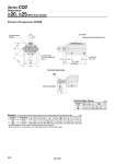
S U E M K L oT oD H1 C1 X L1 Q MM 6.8 13.6 2.7 5.5 A + Stroke B + Stroke V Minimum lead wire bending radius 10 Width across flat B1 Auto switch 2 x M5 x 0.8 (Port size) H thread effective depth C 2 x o5.5 through 2 x 2 x o9 counterbore depth 7 (mm) 20 25 H1 5 6 C1 12 15 B1 13 17 MM M8 x 1.25 M10 x 1.25 X 14 17.5 L1 23.5 27.5 (mm) 20 25 5 to 50 5 to 50 A 51 52.5 B 41.5 42.5 C 7 12 D 10 12 E 47 52 H M5 x 0.8 M6 x 1.0 K 8 10 L 9.5 10 M 36 40 Q 18 19 S 35.5 40.5 T 16.1 18.1 18 21 V 36 40 U o20, o25/With Auto Switch Standard (Through-hole): CDQ2B Dimensions Rod end male thread Rod End Male Thread Bore size (mm) Standard For auto switch proper mounting position and its mounting height, refer to pages 954 to 960. Bore size (mm) Stroke range (mm) . For details about the rod end nut and accessory brackets, refer to page 804. . Refer to page 942 for the calculation on the longitudinal dimension of intermediate strokes. Series CQ2 948