2-p0777-0973-cq2-z_en 209 / 248
10秒後にBOOKのページに移動します
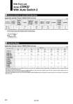
Number of auto switches With 1 pc. With 2 pcs. 5 5 5 10 10 15 15(5) 15(5) 15 20 20(10) 20(15) 15 15 D-M9尰V D-F7尰V D-J79C D-A9尰V D-A7尰 D-A80 D-A73C D-A80C D-M9尰WV D-M9尰AV D-F7尰WV D-F7BAV D-M9尰 D-F7尰 D-J79 15(10) 15(5) D-M9尰W D-M9尰A 15(5) 15(10) D-A7尰H D-A80H D-A79W D-F7尰W D-J79W D-F7BA D-F79F D-F7NT D-P4DW 10(5) 10 D-A9尰 Note) The dimension stated in ( ) shows the minimum stroke for the auto switch mounting when the auto switch does not project from the end surface of the cylinder body and hinder the lead wire bending space. (Refer to the figure below.) The auto switch and auto switch mounting bracket are ordered separately. (mm) 10 5.5 10 5.5 20 25 32 40 50 63 80 100 D-A9尰(V) D-A79W D-P4DW (mm) D-A7尰(H)(C) D-A80尰(H)(C) D-M9尰(V) D-M9尰W(V) D-M9尰A(V) D-F7尰(V) D-J79(C) D-F7尰W(V) D-F7BA(V) D-F7NT D-F79F . . . . . . 9.5 (9.5) 6 (5.5) 12 13 6 . . . 6 (5.5) 9.5 (9.5) 11 14 6 5 7 (6) 9.5 (8.5) 10 14 6 5 7.5 (6.5) 11.5 (11) 12 16 6.5 5 8 (7) 9 (10) 12 15 6.5 5 8.5 (7) 11.5 (10.5) 13 17 7 5.5 Applicable Cylinder Series: CDBQ2 (With end lock) 2 Minimum Stroke for Auto Switch Mounting Applicable Cylinder Series: CDBQ2 (With end lock) . Values which include hysteresis are for guideline purposes only, they are not a guarantee (assuming approximately ±30% dispersion) and may change substantially depending on the ambient environment. . The values for o32 or more of the D-A9尰(V)/M9尰(V)/M9尰W(V)/M9尰A(V) types indicate the operating range when the conventional switch installation groove is attached without using the auto switch mounting bracket BQ2-012. . The values in parentheses for o32 or more of the D-A9尰(V)/M9尰(V)/M9尰W(V)/M9尰A(V) types indicate the operating range when the auto switch mounting bracket BQ2-012 is used. Auto switch model 3 Operating Range Bore size With End Lock Series CDBQ2 With Auto Switch 2 938