2-p0777-0973-cq2-z_en@@@206 / 248
10bÐèBOOKäy[WèÖÛçÉñ
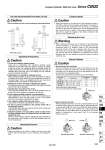
W W Use the Recommended Pneumatic Circuit Caution Operating Precautions Caution Caution 1. Do not use 3-position solenoid valves. Avoid use in combination with 3-position solenoid valves (especially closed center metal seal types). If pressure is trapped in the port on the lock mechanism side, the cylinder cannot be locked. Furthermore, even after being locked, the lock may be released after some time, due to air leaking from the solenoid valve and entering the cylinder. 2. Back pressure is required for releasing the lock. Before starting operation, be sure to control the system so that air is supplied to the side without the lock mechanism as shown in the above figure. There is a possibility that the lock may not be released. (Refer to the section on releasing the lock.) 3. Release the lock for mounting or adjusting the cylinder. If mounting or other work is performed when the cylinder is locked, the lock unit may be damaged. 4. Operate with a load ratio of 50% or less. If the load ratio exceeds 50%, this may cause problems such as failure of the lock to release, or damage to the lock unit. 5. Do not operate multiple cylinders in synchronization. Avoid applications in which two or more end lock cylinders are synchronized to move one work piece, as one of the cylinder locks may not be able to release when required. 6. Use a speed controller with meter-out control. Lock cannot be released occasionally by meter-in control. 7. Be sure to operate completely to the cylinder stroke end on the side with the lock. If the cylinder piston does not reach the end of stroke, locking and unlocking may not be possible. 8. Adjust the position of an auto switch, so that it could work at the both positions where it is distanced from the stroke and a backlash (2 mm). When a 2-color indication switch is adjusted for green indication at the stroke end, it may change to red for the backlash return, but this is not abnormal. . This is necessary for the correct locking and unlocking actions. Operating Pressure 1. Supply air pressure of 0.15 MPa or higher to the port on the side that has the lock mechanism, as it is necessary for releasing the lock. Exhaust Speed 1. When the pressure on the side with the lock mechanism drops to 0.05 MPa or below, the lock engages automatically. If the piping on the side with the lock mechanism is thin and long, or if the speed controller is away from the cylinder port, the lock engagement may take some time due to decline of the exhaust speed. The same result will be caused by clogging of the silencer installed at the EXH port of the solenoid valve. Releasing the Lock Warning Manual Release Caution 1. Manual release (Non-lock type) Insert the accessory bolt from the top of the rubber cap (it is not necessary to remove the rubber cap), and after screwing it into the lock piston, pull it to release the lock. If you stop pulling the bolt, the lock will return to an operational state. Thread sizes, pulling forces and strokes are as shown below. 2. Manual release (Lock type) While pushing the M/O knob, turn it 90 counterclockwise. The lock is released (and remains in a released state) by aligning the mark on the cap with the OFF mark on the M/O knob. When locking is desired, turn the M/O knob clockwise 90 while pushing fully, correspond on cap and ON mark on the M/O knob. The correct position is confirmed by a click sound gclickh. If not confirmed, locking is not done. With head end lock With rod end lock 1. Before releasing the lock, be sure to supply air to the side without the lock mechanism, so that there is no load applied to the lock mechanism when it is released. (Refer to the recommended pneumatic circuits.) If the lock is released when the port on the other side is in an exhaust state, and with a load applied to the lock unit, the lock unit may be subjected to an excessive force and be damaged. Also, it is very dangerous because the piston rod will be rushed to move. Rubber cap Unlock Lock Remove the bolt for normal operation. It can cause lock malfunction or faulty release. Bore size (mm) 20, 25, 32 40, 50, 63 80, 100 M2.5 x 0.45 x 25 L or more M3 x 0.5 x 30 L or more M5 x 0.8 x 40 L or more Thread size 4.9 10 24.5 Pulling force (N) 2 3 3 Stroke (mm) Caution Compact Cylinder: With End Lock Series CBQ2 Manually locked state Manually unlocked state 935 CUJ CU CQS RQ CQM CQU MU -Z D-ÞÛ -XÞÛ Technical data CQ2 -Z