2-p0777-0973-cq2-z_enЃ@Ѓ@Ѓ@193 / 248
10•bЊг‚ЙBOOK‚МѓyЃ[ѓW‚Й€Ъ“®‚µ‚Ь‚·
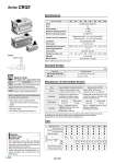
-XB10 -XC26 -XC85 Symbol Specifications Symbol Rubber bumper Bore size (mm) Mounting Piping Through-hole (Standard) Built-in magnet Both ends tapped style Rod end male thread With rubber bumper (Standard) Screw-in type 20 р— р— р— . . р— р— 25 р— р— р— . . р— р— 32 р— р— р— NPT1/8 G1/8 р— р— 40 р— р— р— NPT1/8 G1/8 р— р— 50 р— р— р— NPT1/4 G1/4 р— р— 63 р— р— р— NPT1/4 G1/4 р— р— 80 р— р— р— NPT3/8 G3/8 р— р— 100 р— р— р— NPT3/8 G3/8 р— р— M5 x 0.8 M5 x 0.8 Rc 1/8 Rc 1/8 Rc 1/4 Rc 1/4 Rc 3/8 Rc 3/8 Type . TN TF Refer to pages 936 to 940 for the specifications of cylinders with autoswitches. . Auto switch proper mounting position (detection at stroke end) and its mounting height . Minimum stroke for auto switch mounting . Operating range . Auto switch mounting brackets/Part no. With split pins for double clevis pin/ double knuckle joint pin and flat washers Intermediate stroke (Using exclusive body) Grease for food processing equipment Action Fluid Proof pressure Maximum operating pressure Minimum operating pressure Ambient and fluid temperature Lubrication Piston speed Allowable kinetic energy (J) Stroke length tolerance Lock position Holding force (Max.) (N) Backlash Manual release Bore size (mm) 20 25 32 40 50 63 80 100 Note) 0.05 MPa except for the end lock unit 0.055 0.09 0.15 0.26 0.46 0.77 1.36 Double acting, Single rod Air 1.5 MPa 1.0 MPa 0.15 MPa Note) Not required (Non-lube) 50 to 500 mm/s Head end, Rod end 2 mm or less Non-lock type, Lock type 2.27 Without auto switch: .10 to 70Ѓ‹C (No freezing) With auto switch: .10 to 60Ѓ‹C (No freezing) 215 330 550 860 1340 2140 3450 5390 Specifications +1.0 mm 0 Bore size 20, 25, 32, 40, 50, 63 80, 100 Standard stroke 10, 15, 20, 25, 50, 75, 100 25, 50, 75, 100 Standard Strokes (mm) Manufacture of Intermediate Strokes A spacer is installed in the standard stroke body. Stroke range Example Type Part no. Description Refer to ЃgHow to OrderЃh for the standard model number. (P. 925) Part no.: CBQ2B40-45DC-HL CBQ2B40-50DC-HL with 5 mm width spacer inside. B dimension is 125 mm. Bore size 20 to 100 Stroke range 5 to 95 Strokes in 5 mm intervals are available by installing a spacer in the standard stroke cylinder. Exclusive body (-XB10) Suffix Ѓg-XB10Ѓh to the end of standard model no. on page 925. Part no.: CBQ2B40-45DC-HL-XB10 Makes 45 stroke tube. B dimension is 120 mm. Bore size 20 to 100 Stroke range 6 to 99 Dealing with the stroke by the 1 mm interval by using an exclusive body with the specified stroke. In the case of an exclusive body type for o20, o25, o80 and o100 (-XB10) with the stroke length exceeding 25 mm, the reference values of the longitudinal dimension will be changed. Subtract from 50, 75 and 100 stroke dimensions and figure it out. Series CBQ2 Pneumatic Made to Order (For details, refer to pages 1699 to 1818.) When operating an actuator with a small diameter and a short stroke at a high frequency, the dew condensation (water droplet) may occur inside the piping depending on the conditions. Simply connecting the moisture control tube to the actuator will prevent dew condensation from occurring. For details, refer to Series IDK in the WEB catalog. Moisture Control Tube Series IDK A 926