2-p0777-0973-cq2-z_en 177 / 248
10秒後にBOOKのページに移動します
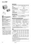
Rubber bumper 32 . TN TF 40 50 63 80 100 Built-in One-touch Fittings Note 2) -XA尰 -XB10 -XC6 -XC26 -XC27 -XC85 Symbol Specifications Made to Order (For details, refer to pages 1699 to 1818.) -X271 Fluororubber seals Symbol Specifications 5, 10, 15, 20, 25, 30, 35, 40, 45, 50, 75, 100 10, 15, 20, 25, 30, 35, 40, 45, 50, 75, 100 (mm) 32, 40 50, 63, 80, 100 Bore size Standard stroke Standard Strokes 1. For installation and removal, use an appropriate pair of pliers (tool for installing a type C retaining ring). 2. Even if a proper plier (tool for installing a type C retaining ring) is used, it is likely to inflict damage to a human body or peripheral equipment, as a retaining ring may be flown out of the tip of a plier (tool for installing a type C retaining ring). Be much careful with the popping of a retaining ring. Besides, be certain that a retaining ring is placed firmly into the groove of rod cover before supplying air at the time of installment. Caution Retaining Ring Installation/Removal Action Fluid Proof pressure Maximum operating pressure Minimum operating pressure Ambient and fluid temperature Lubrication Piston speed Allowable kinetic energy (J) Stroke length tolerance Bore size (mm) 32 40 50 63 80 100 Note) Stroke length tolerance does not include the amount of dumper change. 0.29 0.52 0.91 1.54 2.71 4.54 Double acting, Single rod Air 1.5 MPa 1.0 MPa 0.05 MPa Not required (Non-lube) 50 to 500 mm/s Without auto switch: .10 to 70°C (No freezing) With auto switch: .10 to 60°C (No freezing) +1.0 mm 0 Note) Specifications . In the case of exclusive body type with o32 to o100 (-XB10) with the stroke length exceeding 50 mm, reference values of the longitudinal dimension will be changed. Calculate length dimensions by deducting from those of 75 or 100 mm stroke models. Note 1) The dimension of the o32-5 mm stroke with built-in One-touch fittings is the same as that of the 10 mm stroke cylinder tube. Note 2) One-touch fittings cannot be replaced. Type Part no. Refer to “How to Order” for the standard model number. (P. 913) Part no.: CQ2BS50-57DCZ CQ2BS50-75DCZ with 18 mm width spacer inside The B dimension is 125.5 mm. Part no.: CQ2BS50-57DCZ-XB10 Makes 57 stroke tube. The B dimension is 107.5 mm. Strokes in 1 mm intervals are available by installing a spacer in the standard stroke cylinder. Strokes in 1 mm intervals are available by using an exclusive body with the specified stroke. Suffix “-XB10” to the end of standard model number. (P. 913) Description Stroke range Bore size 32 to 100 Stroke range 1 to 99 Bore size 32, 40 50 to 100 Stroke range 6 to 99 11 to 99 Example A spacer is installed in the standard stroke body. Exclusive body (-XB10) Manufacture of Intermediate Strokes 傱傱傱 Rc1/8 NPT1/8 G1/8 o6 Note 1) 傱傱傱 Through-hole (Standard) Both ends tapped Built-in magnet Rod end male thread With rubber bumper (Standard) With boss on head end Piping Mounting Bore size (mm) 傱傱傱 Rc1/8 NPT1/8 G1/8 o6 傱傱傱 傱傱傱 Rc1/4 NPT1/4 G1/4 o8 傱傱傱 傱傱傱 Rc1/4 NPT1/4 G1/4 o8 傱傱傱 傱傱傱 Rc3/8 NPT3/8 G3/8 . 傱傱傱 傱傱傱 Rc3/8 NPT3/8 G3/8 . 傱傱傱 Pipe thread . Auto switch proper mounting position (detection at stroke end) and its mounting height . Minimum stroke for auto switch mounting . Operating range . Auto switch mounting brackets/Part no. Refer to pages 954 to 960 for the specifications of cylinders with autoswitches. Type Pneumatic Series CQ2 Intermediate stroke (Exclusive body type) Change of rod end shape Grease for food processing equipment With split pins for double clevis pin/ double knuckle joint pin and flat washers Double clevis pin/Double knuckle joint pin material: Stainless steel 304 Piston rod/Retaining ring/Rod end nut material: Stainless steel Made to Order: Individual Specifications (For details, refer to page 968.) Symbol 914