2-p0777-0973-cq2-z_en 16 / 248
10秒後にBOOKのページに移動します
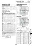
o100 o80 o63 o50 o40 o32 o100 o80 o63 o50 o40 o25 o32 o20 o16 o12 o25 o20 o16 o12 12 16 20 25 32 40 50 63 80 100 Bore size (mm) 5 5 9 15 24 45 64 . . . . 10 6 11 18 28 52 72 117 153 270 487 15 7 13 21 33 60 80 129 165 289 515 20 8 15 24 37 68 88 141 177 308 543 25 10 17 27 42 76 96 153 190 327 570 30 11 19 31 46 84 104 166 202 347 598 35 . . 34 51 92 112 178 214 366 625 40 . . 37 55 100 119 190 226 385 653 45 . . 40 60 107 127 202 239 404 681 50 . . 44 64 115 135 214 251 423 708 75 . . . . 170 190 300 337 557 901 100 . . . . 209 229 361 398 653 1038 Mass of Cylinder Movable Parts/Without Built-in Magnet (g) Cylinder stroke (mm) 12 16 20 25 32 40 50 63 80 100 Bore size (mm) 5 8 16 28 44 78 109 . . . . 10 9 18 31 48 86 117 187 254 433 741 15 10 20 34 53 93 125 199 266 453 768 20 11 22 37 57 101 133 211 278 472 796 25 12 24 40 62 109 140 223 290 491 823 30 13 26 44 66 117 148 236 303 510 851 35 . . 47 71 125 156 248 315 530 879 40 . . 50 75 133 164 260 327 549 906 45 . . 53 80 140 172 272 339 568 934 50 . . 56 84 148 180 285 352 587 962 75 . . . . 187 219 346 413 683 1099 100 . . . . 227 258 407 474 778 1236 Mass of Cylinder Movable Parts/With Built-in Magnet (g) Additional Mass of Cylinder Movable Parts (g) Cylinder stroke (mm) Bore size (mm) 12 1.5 1 0 16 3 2 0 20 6 4 .2 25 12 8 .3 32 26 17 .3 40 27 17 .7 50 53 32 .9 63 53 32 .18 80 120 49 .31 100 175 116 .56 Bore size (mm) 12 0.022 0.043 16 0.038 0.075 20 0.055 0.110 25 0.09 0.18 32 0.15 0.29 40 0.26 0.52 50 0.46 0.91 63 0.77 1.54 80 1.36 2.71 100 2.27 4.54 (J) Standard/ Allowable kinetic energy: Ea With rubber bumper/ Allowable kinetic energy: Eb W (Mounting orientation: Horizontal) If an allowable lateral load at rod end is exceeding the value in the graph, we recommend anti-lateral load type cylinder be used. Cylinder stroke (mm) 100 50 40 30 20 10 5.0 4.0 3.0 2.0 1.0 0.5 0 50 100 Allowable lateral load at rod end W (N) Allowable lateral load at rod end W (N) Cylinder stroke (mm) 200 100 50 40 30 20 10 5.0 4.0 3.0 2.0 1.0 0 50 100 12 16 20 25 32 40 50 63 80 100 Bore size (mm) Operating direction IN OUT IN OUT IN OUT IN OUT IN OUT IN OUT IN OUT IN OUT IN OUT IN OUT 0.3 25 34 45 60 71 94 113 147 181 241 317 377 495 589 841 935 1360 1510 2140 2360 0.5 42 57 75 101 118 157 189 245 302 402 528 628 825 982 1400 1560 2270 2510 3570 3930 0.7 59 79 106 141 165 220 264 344 422 563 739 880 1150 1370 1960 2180 3170 3520 5000 5500 Operating pressure (MPa) (N) With Auto Switch Allowable Kinetic Energy Load Mass and Piston Speed Kinetic energy E (J) = m1 : Mass of cylinder movable parts kg m2 : Load mass kg V : Piston speed m/s (m1+m2) V2 2 Rod end male thread With rubber bumper Male thread Nut Calculation: (Example) CDQ2B32-20DCMZ . Basic mass: CDQ2B32-20DZ . Additional mass: Rod end male thread With rubber bumper 101 g 43 g .3 g 141 g Allowable Lateral Load at Rod End Without Auto Switch Theoretical Output Series CQ2 Compact Cylinder: Standard Double Acting, Single Rod 789 CUJ CU CQS RQ CQM CQU MU -Z D- -X Technical data CQ2 -Z