2-p0777-0973-cq2-z_en 161 / 248
10秒後にBOOKのページに移動します
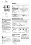
Symbol Spring return Spring extend -XA -XC6 -XC36 -XC85 Symbol Specifications Made to Order (For details, refer to pages 1675 to 1818.) -X271 Fluororubber seals Symbol Specifications Mounting/Removal 1. Do not remove the hexagon socket set screw on the side of the rod. . Be aware that if the hexagon socket set screw is removed with compressed air supplied to the cylinder, an internal steel ball could fly out or the compressed air could be discharged, leading to injury to humans or damage to peripheral equipment. Action Fluid Proof pressure Maximum operating pressure Minimum operating pressure (MPa) Ambient and fluid temperature Lubrication Piston speed Allowable kinetic energy (J) Stroke length tolerance Bore size (mm) 12 16 20 25 32 40 50 0.022 0.038 0.055 0.09 0.15 0.26 Double acting, Single rod Air 1.5 MPa 1.0 MPa Not required (Non-lube) 50 to 500 mm/s 0.46 0.25 0.25 0.18 0.18 0.17 0.15 0.13 Without auto switch: .10 to 70°C (No freezing) With auto switch: .10 to 60°C (No freezing) +1.0 mm 0 Specifications Bore size Standard stroke 5, 10 10, 20 (mm) 12, 16, 20, 25, 32, 40 50 Standard Strokes Type Part no. Description Stroke range Example A spacer is installed in the standard stroke body. Refer to “How to Order” for the standard model number. (P. 897) Strokes in 1 mm intervals are available by installing a spacer in the standard stroke cylinder. Part no.: CQP2B20-3T CQP2B20-5T with 2 mm width spacer inside The B dimension is 24.5 mm. Bore size 12 to 40 50 Stroke range 1 to 9 1 to 19 Manufacture of Intermediate Strokes (Except single acting, spring return) Bore size (mm) Mounting Through-hole (Standard) Built-in magnet Piping Pipe thread Rod end male thread 12 M5 x 0.8 16 M5 x 0.8 20 M5 x 0.8 25 M5 x 0.8 32 Rc1/8 NPT1/8 G1/8 40 Rc1/8 NPT1/8 G1/8 50 Rc1/4 NPT1/4 G1/4 Type Pneumatic Series CQP2 Change of rod end shape Piston rod/Retaining ring/Rod end nut material: Stainless steel With boss on rod end Grease for food processing equipment Made to Order: Individual Specifications (For details, refer to page 968.) Caution Retaining Ring Installation/Removal 1. For installation and removal, use an appropriate pair of pliers (tool for installing a type C retaining ring). 2. Even if a proper plier (tool for installing a type C retaining ring) is used, it is likely to inflict damage to a human body or peripheral equipment, as a retaining ring may be flown out of the tip of a plier (tool for installing a type C retaining ring). Be much careful with the popping of a retaining ring. Besides, be certain that a retaining ring is placed firmly into the groove of rod cover before supplying air at the time of installment. . Auto switch proper mounting position (detection at stroke end) and its mounting height . Minimum stroke for auto switch mounting . Operating range . Auto switch mounting brackets/Part no. Refer to pages 908 to 912 for the specifications of cylinders with autoswitches. When operating an actuator with a small diameter and a short stroke at a high frequency, the dew condensation (water droplet) may occur inside the piping depending on the conditions. Simply connecting the moisture control tube to the actuator will prevent dew condensation from occurring. For details, refer to Series IDK in the WEB catalog. Moisture Control Tube Series IDK A 898