2-p0777-0973-cq2-z_enü@ü@ü@15 / 248
10ĢbīŃé╔BOOKé╠āyü[āWé╔ł┌ō«éĄé▄éĘ
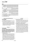
1. For installation and removal, use an appropriate pair of pliers (tool for installing a type C retaining ring). 2. Even if a proper plier (tool for installing a type C retaining ring) is used, it is likely to inflict damage to a human body or peripheral equipment, as a retaining ring may be flown out of the tip of a plier (tool for installing a type C retaining ring). Be much careful with the popping of a retaining ring. Besides, be certain that a retaining ring is placed firmly into the groove of rod cover before supplying air at the time of installment. Retaining Ring Installation/Removal Mounting Caution The CQ2 series compact cylinders are designed to create compact mechanical equipment and promote space saving. Thus, if it is used in the same manner as conventional cylinders such as tie-rod cylinders, it may degrade the performance. Pay sufficient attention to the operating conditions when using. Caution 1. Allowable lateral load Lateral load that can apply to the piston rod end is limited. If a cylinder is used witha lateral load over the limit, it may cause air leakage due to abnormal friction of seals, galling of cylinder tubes and pistons, or abnormal friction of the bearing part. The lateral load applied to the piston rod must be within the allowable range indicatedin this catalog. When the load exceeds the limit, use a double rod cylinder, install a guide, or change the bore size to suit the load in order to make the load within the allowable range. As a standard product, an anti-lateral load type cylinder that is resistant to approx. 2 times more than the conventional compact CQ2 series is also available (page 913). Mounting 2. Connection with a work piece When a work piece is mounted on the piston rod end, connect them aligning the center of piston rod and a work piece. If they are off-center, lateral load is generated and phenomena mentioned in (1) may occur. In order not to apply the off-center load, use of a floating joint or simple joint is recommended. 3. Simultaneous use of multiple cylinders It is difficult to control the speed of pneumatic cylinders. The following conditions cause speed change: change in supply pressure, load, temperature and lubrication, performance difference of each cylinder, deterioration of each part over time, etc. Aspeed controller can be used to control the speed of multiple cylinders simultaneously for a short period of time, but depending on conditions, it may not work as desired. If multiple cylinders cannot operate simultaneously, unreasonable force is applied to the piston rod because cylinder positions may not be the same. This may cause abnormal friction of seals and bearings, and galling of cylinder tubes and pistons. Do not use an application to operate several cylinders simultaneously by adjusting cylinder speed. If this is inevitable, use a high rigid guide against load, so that the cylinder is not damaged even when the each cylinder output is slightly different. Series CQ2 Bore size (mm) Mounting Piping Mounting Piping Through-hole (Standard) Both ends tapped style Through-hole (Standard) Both ends tapped style Built-in magnet Built-in magnet Rod end male thread With rubber bumper Rod end male thread Screw-in type Screw-in type Built-in One-touch fittings Note 3) 12 Ś Ś Ś . . . Ś Ś . . . . . . 16 Ś Ś Ś . . . Ś Ś . . . . . . 20 Ś Ś Ś . . . Ś Ś Ś Ś Ś . Ś 25 Ś Ś Ś . . . Ś Ś Ś Ś Ś . Ś 32 Ś Ś Ś NPT1/8 G1/8 o6 Note 2) Ś Ś Ś Ś Ś NPT1/8 Ś 40 Ś Ś Ś NPT1/8 G1/8 o6 Ś Ś Ś Ś Ś NPT1/8 Ś 50 Ś Ś Ś NPT1/4 G1/4 o8 Ś Ś Ś Ś Ś NPT1/4 Ś 63 Ś Ś Ś NPT1/4 G1/4 o8 Ś Ś Ś Ś Ś NPT1/4 Ś 80 Ś Ś Ś NPT3/8 G3/8 . Ś Ś Ś Ś Ś NPT3/8 Ś 100 Ś Ś Ś NPT3/8 G3/8 . Ś Ś Ś Ś Ś NPT3/8 Ś M5 x 0.8 M5 x 0.8 M5 x 0.8 M5 x 0.8 M5 x 0.8 M5 x 0.8 Note 1) M5 x 0.8 Rc1/8 Note 1) M5 x 0.8 Rc1/8 Rc 1/8 Rc 1/8 Rc 1/4 Rc 1/4 Rc 1/4 Rc 1/4 Rc 3/8 Rc 3/8 Rc 3/8 Rc 3/8 Note 1) For a o32 cylinder without an auto switch, M5 x 0.8 is used for 5-stroke piping dimension. Thus, do not enter a symbol for the port tread type. Note 2) The dimension of the o32-5 mm stroke with built-in One-touch fittings is the same as that of the 10 mm stroke cylinder tube. Note 3) One-touch fittings cannot be replaced. . TN . TN TF Type Air-hydro Pneumatic A 788