2-p0777-0973-cq2-z_en 140 / 248
10秒後にBOOKのページに移動します
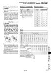
12 16 20 25 32 40 50 63 25 45 71 113 181 317 495 841 0.3 42 75 118 189 302 528 825 1400 0.5 59 106 165 264 422 739 1150 1960 0.7 12 16 20 25 32 40 50 63 5 62 62 101 138 233 336 . . 10 69 73 116 155 256 365 517 742 15 76 84 131 172 279 394 558 779 20 83 95 146 189 302 424 600 815 25 90 106 161 206 325 453 642 851 30 97 117 176 223 348 483 684 887 35 . . 191 240 371 512 725 923 40 . . 206 257 394 541 767 959 45 . . 221 274 417 571 809 995 50 . . 236 291 440 600 850 1032 75 . . . . 600 806 1142 1285 100 . . . . 715 953 1351 1465 Caution 1. For installation and removal, use an appropriate pair of pliers (tool for installing a type C retaining ring). 2. Even if a proper plier (tool for installing a type C retaining ring) is used, it is likely to inflict damage to a human body or peripheral equipment, as a retaining ring may be flown out of the tip of a plier (tool for installing a type C retaining ring). Be much careful with the popping of a retaining ring. Besides, be certain that a retaining ring is placed firmly into the groove of rod cover before supplying air at the time of installment. Retaining Ring Installation/Removal 1. Do not apply reverse torque to the piston rods sticking out from both sides of this cylinder at the same time. The torque makes connection threads inside loosen, which may cause an accident or malfunction. Install or remove loads while the piston rod width across flat is secured. Also, tighten by giving consideration to prevent the tightening torque from being applied to the nonrotating guide. Do not fix the other side of the piston rod width across flat and apply reverse torque. Warning Mounting 2. Using a non-rotating rod cylinder Avoid using the air cylinder in such a way that rotational torque would be applied to the piston rod. If rotational torque is applied, the non-rotating guide will deform, causing a loss of non-rotating accuracy. Use the below table as a guide for the allowable rotational torque ranges. Allowable rotational torque N・m or less o12 o16 o20 o25 o32 o40 o50 o63 0.04 0.15 0.20 0.25 0.44 0.44 0.44 0.44 (N) Mounting Brackets/Part No. Theoretical Output Note 1) When ordering foot and compact foot brackets, order 2 pieces per cylinder. Note 2) Parts belonging to each bracket are as follows. Foot, Compact foot, Flange: Body mounting bolts Bore size (mm) Operating pressure (MPa) Weight (g) Bore size (mm) Cylinder stroke (mm) Weight Additional Weight (g) Calculation: (Example) CQ2KWA40-20DMZ . Basic weight: CQ2KWB40-20DZ ・・・・・・・・・・・・ 424 g . Additional weight: Both ends tapped ・・・・・・・・・・・・・・・・ 6 g Rod end male thread ・・・・・・・・・ 88 g 518 g Series CQ2KW Compact Cylinder: Non-rotating Rod Double Acting, Double Rod Bore size (mm) Foot Note 1) Flange 40 50 63 CQ-L040 CQ-L050 CQ-L063 Compact foot Note 1) CQ-LC040 CQ-LC050 CQ-LC063 CQ-F040 CQ-F050 CQ-F063 Bore size (mm) Both ends tapped Rod end male thread Male thread Nut Foot (Including mounting bolts) Compact foot (Including mounting bolts) Flange (Including mounting bolts) Built-in One-touch fittings 12 . 3 2 . . . . 16 . 6 4 . . . . 20 . 12 8 . . . . 25 . 24 16 . . . . 32 . 52 34 12 . . . 40 6 54 34 12 154 114 214 50 6 106 64 21 243 177 373 63 19 106 64 21 317 241 559 879 CUJ CU CQS RQ CQM CQU MU -Z D- -X Technical data CQ2 -Z A