2-p0777-0973-cq2-z_enЃ@Ѓ@Ѓ@139 / 248
10•bЊг‚ЙBOOK‚МѓyЃ[ѓW‚Й€Ъ“®‚µ‚Ь‚·
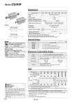
Symbol Without cushion Rubber bumper . -X633: Intermediate stroke in 5 mm intervals only -XAр -XB10 -XC2(A) Change of rod end shape Intermediate stroke (Exclusive body type) Rod end length, 10 mm increased (For foot and flange bracket) Symbol Specifications Made to Order (For details, refer to pages 1675 to 1818.) -X633 Intermediate stroke of double rod cylinder Symbol Specifications Made to Order: Individual Specifications (For details, refer to page 971.) (mm) 5, 10, 15, 20, 25, 30 5, 10, 15, 20, 25, 30, 35, 40, 45, 50 5, 10, 15, 20, 25, 30, 35, 40, 45, 50, 75, 100 10, 15, 20, 25, 30, 35, 40, 45, 50, 75, 100 Action Fluid Proof pressure Maximum operating pressure Minimum operating pressure Ambient and fluid temperature Lubrication Piston speed Allowable kinetic energy (J) Stroke length tolerance Rod non-rotating accuracy Bore size (mm) 12 16 20 25 32 40 50 63 . o12 with auto switch: With rubber bumper (Standard) Note 1) For cylinders with rubber bumper (o12 with auto switch only) Note 2) Stroke length tolerance does not include the amount of bumper change. 0.022 0.043 Note 1) 0.038 0.055 0.09 0.15 0.26 Double acting, Double rod Air 1.5 MPa 1.0 MPa Not required (Non-lube) 50 to 500 mm/s 0.46 0.77 0.07 MPa 0.05 MPa Without auto switch: .10 to 70Ѓ‹C (No freezing) With auto switch: .10 to 60Ѓ‹C (No freezing) Ѓ}2Ѓ‹ Ѓ}1Ѓ‹ Ѓ}0.8Ѓ‹ Specifications +1.0 mm 0 Note 2) Bore size Standard stroke 12, 16 20, 25 32, 40 50, 63 Standard Strokes A spacer is installed in the standard stroke body. Refer to ЃgHow to OrderЃh for the standard model number. (P. 877) Strokes in 5 mm intervals are available by installing a spacer in the standard stroke cylinder. Part no.: CQ2KWB50-65DZ CQ2KWB50-75DZ with 10 mm width spacer inside The B dimension is 125.5 mm. Bore size 32 to 63 Stroke range 55 to 95 Type Part no. Description Stroke range Example Manufacture of Intermediate Strokes Bore size (mm) Mounting Through-hole (Standard) Both ends tapped Built-in magnet Piping Pipe thread Built-in one-touch fittings Rod end male thread 12 р‘ р‘ M5 x 0.8 р‘ 16 р‘ р‘ M5 x 0.8 р‘ 20 р‘ р‘ M5 x 0.8 р‘ 25 р‘ р‘ M5 x 0.8 р‘ 32 р‘ р‘ Note 1) M5 x 0.8 Rc1/8 р‘ NPT1/8 G1/8 NPT1/8 G1/8 NPT1/4 G1/4 NPT1/4 G1/4 40 р‘р‘р‘ Rc1/8 o6 р‘ 50 р‘р‘р‘ Rc1/4 o8 р‘ 63 р‘р‘р‘ Rc1/4 o8 р‘ o6 Note 2) . Auto switch proper mounting position (detection at stroke end) and its mounting height . Minimum stroke for auto switch mounting . Operating range . Auto switch mounting brackets/Part no. Refer to pages 954 to 960 for the specifications of cylinders with autoswitches. Note 1) o32 without auto switch: M5 x 0.8 is used for 5 mm stroke piping dimension. Thus, do not enter a symbol for the port thread type. Note 2) The dimensions of the o32-5 mm stroke with built-in One-touch fittings are the same as those of the 10 mm stroke cylinder tube. . TN TF Type Pneumatic Series CQ2KW When operating an actuator with a small diameter and a short stroke at a high frequency, the dew condensation (water droplet) may occur inside the piping depending on the conditions. Simply connecting the moisture control tube to the actuator will prevent dew condensation from occurring. For details, refer to Series IDK in the WEB catalog. Moisture Control Tube Series IDK A 878