2-p0777-0973-cq2-z_en 124 / 248
10秒後にBOOKのページに移動します
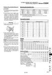
12 16 20 25 32 40 50 63 5 10 15 20 25 30 35 40 45 50 75 100 60 58 103 137 196 205 . . 67 67 117 152 215 226 356 524 74 76 131 167 234 248 390 563 81 85 145 182 253 269 424 602 88 94 159 197 272 291 457 641 95 103 173 212 291 312 491 680 . . 187 227 310 333 525 720 . . 201 242 329 355 559 759 . . 215 257 347 376 592 798 . . 229 272 366 398 626 837 . . . . 506 570 901 1173 . . . . 601 682 1075 1375 Caution 1. For installation and removal, use an appropriate pair of pliers (tool for installing a type C retaining ring). 2. Even if a proper plier (tool for installing a type C retaining ring) is used, it is likely to inflict damage to a human body or peripheral equipment, as a retaining ring may be flown out of the tip of a plier (tool for installing a type C retaining ring). Be much careful with the popping of a retaining ring. Besides, be certain that a retaining ring is placed firmly into the groove of rod cover before supplying air at the time of installment. Retaining Ring Installation/Removal Mounting 1. Install or remove loads while the piston rod width across flat is secured. 2. Using a non-rotating rod cylinder Avoid using the air cylinder in such a way that rotational torque would be applied to the piston rod. If rotational torque is applied, the non-rotating guide will deform, causing a loss of non-rotating accuracy. Use the below table as a guide for the allowable rotational torque ranges. Operate the cylinder in such a way that the load to the piston rod is always applied in the axial direction. 3. When a work piece is secured to the end of the piston rod, ensure that the piston rod is retracted entirely, and place a wrench on the portion of the rod that protrudes beyond the section. Also, tighten in a way that prevents the tightening torque from being applied to the non-rotating guide. Allowable rotational torque N・m or less 12 16 20 25 32 40 50 63 0.04 0.15 0.20 0.25 0.44 0.44 0.44 0.44 Weight (g) Bore size (mm) Cylinder stroke (mm) Weight Additional Weight (g) 269 g 6 g 44 g 196 g 515 g Calculation: (Example) CQ2KD40-20DMZ . Basic weight: CQ2KB40-20DZ ・・・・・・・・・・・・・・・・ . Additional weight: Both ends tapped ・・・・・・・・・・・・・・・・・・ Rod end male thread ・・・・・・・・・・・ Double clevis ・・・・・・・・・・・・・・・・・・・・・ Series CQ2K Compact Cylinder: Non-rotating Rod Double Acting, Single Rod (N) Bore size (mm) Operating direction 0.3 25 34 45 60 71 94 113 147 181 241 317 377 495 589 841 935 0.5 42 57 75 101 118 157 189 245 302 402 528 628 825 982 1400 1560 0.7 59 79 106 141 165 220 264 344 422 563 739 880 1150 1370 1960 2180 12 16 20 25 32 40 50 63 Operating pressure (MPa) Bore size (mm) Foot Note 1) 40 50 63 CQ-L040 CQ-L050 CQ-L063 Compact foot Note 1) CQ-LC040 CQ-LC050 CQ-LC063 Flange CQ-F040 CQ-F050 CQ-F063 Double clevis CQ-D040 CQ-D050 CQ-D063 Note 1) When ordering foot and compact foot brackets, order 2 pieces per cylinder. Note 2) Parts belonging to each bracket are as follows. Foot, Compact foot, Flange: Body mounting bolts Double clevis: Clevis pin, Body mounting bolts, Type C retaining rings for axis Mounting Brackets/Part No. Theoretical Output IN OUT IN OUT IN OUT IN OUT IN OUT IN OUT IN OUT IN OUT 12 . 1.5 1 0.7 . . 41 . . . 16 . 3 2 1.3 . . 51 . . . 20 . 6 4 2 . . 121 . . . 25 . 12 8 3 . . 140 . . . 32 . 26 17 5 12 . 99 . . . 40 6 27 17 7 12 153 114 213 198 196 50 6 53 32 13 21 242 177 372 348 393 63 19 53 32 25 21 316 241 558 534 554 Bore size (mm) Both ends tapped Rod end male thread With boss on head end Built-in One-touch fittings Foot (Including mounting bolts) Compact foot (Including mounting bolts) Rod flange (Including mounting bolts) Head flange (Including mounting bolts) Double clevis (Including pin, retaining rings, bolts) Male thread Nut 865 CUJ CU CQS RQ CQM CQU MU -Z D- -X Technical data CQ2 -Z A