2-p0777-0973-cq2-z_en 117 / 248
10秒後にBOOKのページに移動します
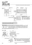
Q Q oTh9 L oD H1 L1 C1 X MM X Y Y X L L1 LG LT LZ LX LY LH W E M K E M Z J 5 B + Stroke A + Stroke 2 x P (Port size) Minimum lead wire bending radius 10 Auto switch Width across flat B1 8 x O thread effective H thread effective depth R depth C Special cap bolt A + Stroke LS + Stroke B + Stroke 4 x oLD (mm) 63 80 100 27 32 41 B1 26 32.5 32.5 C1 11 13 16 H1 MM M18 x 1.5 M22 x 1.5 M26 x 1.5 L1 43.5 53.5 53.5 28.5 35.5 35.5 X (mm) 63 80 100 A B C D E H J K L M O P Q R Th9 W M10 x 1.5 M16 x 2.0 M20 x 2.5 M10 x 1.5 M12 x 1.75 M12 x 1.75 16.5 19 23 18 22 22 84 104 123.5 Z 19 25 25 1/4 3/8 3/8 75 86 97.5 57 66 75.5 15 21 27 20 25 30 77 98 117 7 6 6.5 17 22 27 18 20 22 60 77 94 35 43 59 0 .0.062 0 .0.062 0 .0.074 (mm) 63 80 100 Y 9 11 12.5 X 16.2 19.5 23 LZ 113 140 162 LY 91.5 114 136 LX 95 118 137 LT 3.2 4.5 6 LS 31 36 41.5 LH 46 59 71 LG 5 7 7 LD 11 13 13 L1 43.5 53.5 53.5 L 18 20 22 B 57 66 75.5 A 83.2 97.5 110.5 Dimensions Both ends tapped: CQ2A o63 to o100 The dimensions are the same with or without an auto switch. Rod end male thread Rod End Male Thread Bore size (mm) The dimensions with built-in One-touch fittings are equivalent to those of the CQ2 series, double acting, single rod. Refer to page 802. Note 1) For 125 to 200 strokes, strokes are available in 25 mm intervals. Note 2) For calculation on the longitudinal dimension of intermediate strokes, refer to page 855. Both Ends Tapped For auto switch proper mounting position and its mounting height, refer to pages 954 to 960. Bore size (mm) Stroke range (mm) 125 to 200 Note 1) 250, 300 Foot: CQ2L Rod end male thread . For details about the rod end nut and accessory brackets, refer to page 804. Foot bracket material: Carbon steel Surface treatment: Nickel plated Foot Bore size (mm) Series CQ2 860