2-p0777-0973-cq2-z_en 107 / 248
10秒後にBOOKのページに移動します
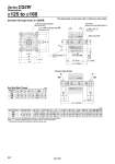
L1 + Stroke A1 + 2 (Stroke) (Also back cover) (Also back cover) 2 x 4 x oOB counterbore depth RB 2 x H thread effective depth C 4 x oN through-hole B + Stroke A + 2 (Stroke) L + Stroke Minimum lead wire bending radius 10 Auto switch Width across flat K 2 x 4 x OA thread depth RA 4 pcs. With flat washer Note 1) (Port size) 2 x P (Rc, NPT, G) MM MM B1 B1 L Q Q oD oD L1 X C1 X C1 H1 H1 K M E J M E W (mm) 125 140 160 199 199 219 46 46 55 58 58 64 45 45 50 A1 B1 M30 x 1.5 M30 x 1.5 M36 x 1.5 L1 MM 42 42 47 18 18 21 C1 H1 X (mm) 125 140 160 H M22 x 2.5 M22 x 2.5 M24 x 3 OA M14 x 2 M14 x 2 M16 x 2 C 30 (22.5) 30 (22.5) 33 (26.5) A 115 115 125 E 142 158 178 10, 20, 30, 40, 50 75, 100, 125, 150 175, 200, 250, 300 B 83 83 91 D 36 36 40 J 11 10 10 K 32 32 36 L 16 16 17 M 114 128 144 N 12.5 12.5 14.5 OB 21.2 21.2 24.2 Q 24.5 24.5 27.5 P 3/8 3/8 3/8 RA 25 25 28 RB 18.4 18.4 21.2 W 153 168 188 2.5 25 Dimensions Standard (Through-hole): CQ2WB The dimensions are the same with or without an auto switch. o125 to o160 Rod end male thread Rod End Male Thread Bore size (mm) Note 1) Be sure to use the attached flat washer for mounting cylinder with through-holes. Note 2) ( ): Values of effective length in one side, only for 10 mm stroke model . The positions of double rod width across flats are not the same. Bore size (mm) Standard stroke Note 2) Series CQ2W 852