2-p0505-0560-ca2_en 49 / 57
10秒後にBOOKのページに移動します
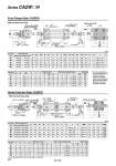
With rod boot (One side) Bore size (mm) 40 50 63 80 100 Without rod boot Up to 500 Up to 600 Up to 600 Up to 750 Up to 750 With rod boot 20 to 500 20 to 600 20 to 600 20 to 750 20 to 750 Stroke range (mm) A 30 35 35 40 40 AL 27 32 32 37 37 FB 71 81 101 119 133 B 60 70 85 102 116 B1 22 27 27 32 41 C 44 52 64 78 92 D 16 20 20 25 30 E 32 40 40 52 52 FD 9.0 9.0 11.5 13.5 13.5 FT 12 12 15 18 18 FX 80 90 105 130 150 FY 42 50 59 76 92 FZ 100 110 130 160 180 FV 60 70 86 102 116 G 15 17 17 21 21 H1 8 11 11 13 16 J M8 x 1.25 M8 x 1.25 M10 x 1.25 M12 x 1.75 M12 x 1.75 K 6 7 7 11 11 Bore size (mm) 40 50 63 80 100 KA 14 18 18 22 26 M 11 11 14 17 17 MM M14 x 1.5 M18 x 1.5 M18 x 1.5 M22 x 1.5 M26 x 1.5 N 27 30 31 37 40 S 84 90 98 116 126 d 52 58 58 80 80 e 43 52 52 65 65 f 15 15 17.5 21.5 21.5 l 1/4 stroke 1/4 stroke 1/4 stroke 1/4 stroke 1/4 stroke ZZ 194 214 222 267 279 H 51 58 58 71 72 ZZ 186 206 214 258 270 h 59 66 66 80 81 (Both sides) ZZ 202 222 230 276 288 Without rod boot With rod boot (Single side) P 1/4 3/8 3/8 1/2 1/2 (mm) Bore size (mm) 40 50 63 80 100 Without rod boot Up to 500 Up to 600 Up to 600 Up to 750 Up to 750 With rod boot 20 to 500 20 to 600 20 to 600 20 to 750 20 to 750 Stroke range (mm) A 30 35 35 40 40 B 60 70 85 102 116 B1 22 27 27 32 41 C 44 52 64 78 92 D 16 20 20 25 30 E 32 40 40 52 52 F 10 10 10 14 14 G 15 17 17 21 21 J M8 x 1.25 M8 x 1.25 M10 x 1.25 M12 x 1.75 M12 x 1.75 K 6 7 7 11 11 MM M14 x 1.5 M18 x 1.5 M18 x 1.5 M22 x 1.5 M26 x 1.5 N 27 30 31 37 40 S 84 90 98 116 126 Bore size (mm) 40 50 63 80 100 TT 22 22 28 34 40 TY 62 74 90 110 130 e 43 52 52 65 65 f 11.2 11.2 11.2 12.5 14.0 h 59 66 66 80 81 Z 101 111 115 138 144 TZ 117 127 148 192 214 H 51 58 58 71 72 ZZ 186 206 214 258 270 Z 93 103 107 129 135 d 56 64 64 76 76 ZZ 194 214 222 267 279 ZZ 202 222 230 276 288 Z 101 111 115 138 144 Without rod boot With rod boot (Single side) TX 85 95 110 140 162 (mm) P 1/4 3/8 3/8 1/2 1/2 (Both sides) TDe8 15 15 18 25 25 -0.032 -0.059 -0.032 -0.059 -0.032 -0.059 -0.040 -0.073 -0.040 -0.073 l 1/4 stroke 1/4 stroke 1/4 stroke 1/4 stroke 1/4 stroke AL 27 32 32 37 37 If a hole is provided to accommodate the boot when the air-hydro cylinder is mounted, make the hole diameter larger than the outside diameter of the boot mounting bracket od. 10.2 ZZ + l + 2 strokes od f oe h + l oE G G M oD oD H1 FT N N H1 AL A K K AL A H FB FV FY CB FX FZ 4 x oFD 4 x J MM MM l G G H1 H1 oE oD oD oE TY oTDe8 CB TX TZ F F AL AL A K K A H N TT N 4 x J MM MM . Do not disassemble the trunnion style. Refer to page 560. ZZ + l + 2 strokes Z + l + 1/2 stroke od 10.2 l f oe h + l Series CA2WH Front Flange Style: CA2WFH S + Stroke H + Stroke ZZ + 2 strokes Air release Width across flats KA Width across flats B1 Width across flats KA Width across flats B1 Center Trunnion Style: CA2WTH With rod boot (One side) Z + 1/2 stroke H + Stroke ZZ + 2 strokes S + Stroke Air release Air release Width across flats KA Width across flats B1 Width across flats KA Width across flats B1 2 x P (Rc, NPT, G) 2 x P (Rc, NPT, G) 552