2-p0505-0560-ca2_en 46 / 57
10秒後にBOOKのページに移動します
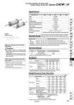
Without cushion Bore size (mm) 40 50 63 80 100 Type Fluid Action Proof pressure Maximum operating pressure Minimum operating pressure Piston speed Ambient and fluid temperature Cushion Stroke length tolerance Mounting Air-hydro Turbine oil Double acting 1.5 MPa 1.0 MPa 0.16 Mpa 0.5 to 300 mm/s 5°C to 60°C Without Basic style, Axial foot style, Rod side flange style, Center trunnion style . Intermediate strokes not listed above are produced upon receipt of order. Bore size (mm) 40 50, 63 80, 100 Standard strokes (mm) Series CA2WH Air-hydro Cylinder: Air-hydro Type Double Acting, Double Rod Specifications To 250 st : + 1 .0 , 251 to 750 st : 0 +1.4 0 Standard Stroke/ In case of a type with auto switch, please also refer to the table of minimum strokes for auto switch mounting on pages 555 and 556. Rod Boot Material . Maximum ambient temperature for the rod boot itself. Symbol J K Rod boot materials Nylon tarpaulin Heat resistant tarpaulin Accessory Standard equipment Options Double knuckle joint (with pin) Rod end nut Single kuckle joint With rod boot Mounting Basic style Foot style Center trunnion style Flange style . The above brackets have the same dimensions as those for the standard double acting single rod Series CA2. Please refer to page 519. Calculation: (Example) CA2WLH40-100 (Axial foot style, o40, 100 st) . Basic weight ................1.22 (Axial foot style, o40) . Additional weight ........ 0.30/50 st . Cylinder stroke .......... 100 st 1.22 + 0.30 x 100/50 = 1.82 kg Weight/Aluminum Tube (Steel tube) (kg) Bore size (mm) Basic weight Additional weight per each 50 mm stroke Basic Axial foot Flange Trunnion All mounting brackets (Except steel tube trunnion) Steel tube trunnion Single knuckle Double knuckle (With pin) Accessory 40 50 63 80 100 1.03 (1.08) 1.22 (1.27) 1.40 (1.45) 1.39 (1.49) 0.30 (0.35) (0.44) 0.23 0.37 1.59 (1.64) 1.81 (1.86) 2.05 (2.09) 2.07 (2.18) 0.40 (0.47) (0.58) 0.26 0.43 2.26 (2.30) 2.59 (2.63) 3.05 (3.09) 3.06 (3.25) 0.50 (0.55) (0.77) 0.26 0.43 3.94 (4.09) 4.61 (4.76) 5.39 (5.55) 5.49 (5.78) 0.71 (0.89) (1.06) 0.60 0.87 5.57 (5.78) 6.65 (6.77) 7.49 (7.70) 7.85 (8.24) 0.92 (1.15) (1.35) 0.83 1.27 . Values inside the parentheses are those for the steel tube type. Max. ambient temperature 70°C 110°C. 25, 50, 75, 100, 125, 150, 175, 200, 250, 300, 350, 400, 450, 500 25, 50, 75, 100, 125, 150, 175, 200, 250, 300, 350, 400, 450, 500, 600 25, 50, 75, 100, 125, 150, 175, 200, 250, 300, 350, 400, 450, 500, 600, 700 Minimum Stroke for Auto Switch Mounting Caution 1.The minimum stroke for mounting varies with the auto switch type and mounting style of the cylinder. In particular, the center trunnion style needs careful attention. (For more information, please refer to page 555.) . Minimum auto switch mounting stroke . Proper auto switch mounting position (detection at stroke end) and mounting height . Operating range . Auto switch mounting bracket: Part no. Refer to pages 553 to 558 for cylinders with auto switches. Symbol 549 CJ1 CJP CJ2 -Z CJ2 CM2 -Z CM2 CM3 CG1 -Z CG1 CG3 MB -Z MB MB1 CA2 -Z CA2 CS1 CS2 D- -X Technical data